15
aSS
embl
y
WIRING THE WINCH
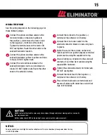
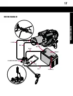
See the wiring diagram on the following page for
these following steps
Connect the yellow and blue cables to the
motor terminals on the winch (yellow to
the positive (+) terminal of the motor; blue
to the negative (-) terminal of the motor).
Tighten the terminal nuts on the motor. DO
NOT overtighten. Route the other ends to the
solenoid/contactor location.
Connect the yellow and blue cables to the
solenoid/contactor (yellow to yellow and blue
to blue). DO NOT tighten nuts.
Connect the red and black cables to the
solenoid/contactor (red to red and black to
black). DO NOT tighten nuts. Route the other
ends to the vehicle’s battery.
1
2
3
4
9
5
6
7
8
CAUTION!
never route electrical cables across any sharp edges, through and/or near moving parts, or near parts
that may become hot.
battery cables should not be drawn tight. leave some slack for cable movement.
NOTICE:
you may need to use a test light to locate a suitable wire. the wire should only have power when the key
is in the on position.
Connect the red lead to the positive (+)
terminal of the vehicle’s 12V battery.
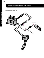
Connect the mini-rocker switch to the
solenoid/contactor (black to black and green
to green).
Splice the end of the red wire on the mini-
rocker switch to an ignition (keyed) controlled
power source using the supplied wire tap.
Once all wiring is connected to the solenoid/
contactor, it can then be mounted using the
supplied M6 hardware.
Tighten the solenoid/contactor terminal nuts.
DO NOT overtighten.
Connect the black lead to the negative (-)
terminal of the vehicle’s 12V battery.
Place all terminal boots over terminals and
secure all cables with cable ties or electrical
tape (not included).
10


