background image

บ٢ʰʕʍʒɁႱࢠ

HYDRAULIC UNIT ALARMS

194

2

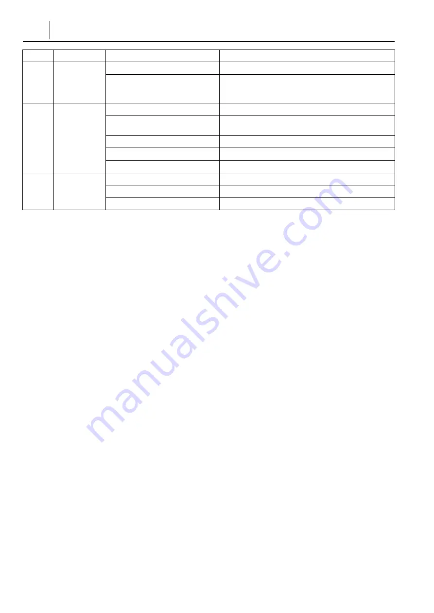
Pressure 
fluctuation

Air entry into piping

Item 4

Pressure gage reading abnormal

Item 1
When necessary to replace the pressure gage, contact the 
Mori Seiki Service Department for assistance.

3

Abnormal 
noise 
generated

Hydraulic oil viscosity inappropriate

“OILS” (page 59)

Low oil level in tank

“Checking Oil Level/Replenishing Oil” (page 94), 
“Replacing Oil” (page 94)

Suction strainer clogging

“Cleaning Suction Strainer and Tank” (page 96)

Pressure fluctuation

Item 2

Pump component damage/wearing

Contact the Mori Seiki Service Department for assistance.

4

Oil leakage

Oil leakage from connections

Tighten connections.

Hose deterioration, damage

Contact the Mori Seiki Service Department for assistance.

Oil leakage from pump

Contact the Mori Seiki Service Department for assistance.

Item

Status

Cause

Reference Items/Recovery Procedures

Summary of Contents for NL1500/500

Page 1: ...250 NL2500MC 1250 NL2500Y 1250 NL2500S 1250 NL2500SMC 1250 NL2500SY 1250 NL3000 700 NL3000MC 700 NL3000Y 700 NL3000 1250 NL3000MC 1250 NL3000Y 1250 NL3000 2000 NL3000MC 2000 NL3000Y 2000 NL3000 3000 N...

Page 2: ...part of the manual is unclear please contact Mori Seiki and clarify these points before using the machine Mori Seiki will not be liable for any damages occurring as a direct or indirect consequence of...

Page 3: ...eki Nakamura ku Nagoya City Aichi 450 0002 Japan Contact Address for Inquiry Regarding Technical Files MORI SEIKI GmbH Head Office Antoniusstrasse 14 73249 Wernau Germany Phone 49 7153 934 0 Fax 49 71...

Page 4: ...SEIKI Turkey DMG MOR SE K STANBUL MAK NE T CARET VE SERV S L M TED RKET Head Office Technical Center Ferhatpa a Mah Gazipa a Cad No 11 34885 Ata ehir stanbul Turkey Phone 90 216 471 66 36 Fax 90 216...

Page 5: ...re This machine is suitable for manual and automatic operation Tools This machine is capable of using common turning tools and rotary tools such as milling cutters drills and taps Contact Mori Seiki b...

Page 6: ...vements to the machine All rights reserved reproduction of this instruction manual in any form is not permitted without the written consent of Mori Seiki Various manuals and documents are supplied wit...

Page 7: ...s injury 7 7 CAUTION Indicates a potentially hazardous situation which if not avoided may result in minor injury or damage to the machine 2 2 NOTE Indicates items that must be taken into consideration...

Page 8: ......

Page 9: ...CONTENTS FOR SAFE MACHINE OPERATION REGULAR MAINTENANCE TROUBLESHOOTING INDEX...

Page 10: ......

Page 11: ...N OFF Power 5 3 28 Bar Stock 5 4 29 Door Interlock Function 5 5 1 30 Safety During Machine Operation 1 5 6 2 31 Safety During Machine Operation 2 5 7 31 Spindle Speed and Chucking 5 8 32 Spindle Speed...

Page 12: ...Equivalents 5 62 LIMIT SWITCH SOLENOID VALVE INSTALLATION POSITIONS 5 1 NL1500 NL2000 NL2500 NL3000 700 NL3000 1250 62 NL1500 NL2000 NL2500 NL3000 700 NL3000 1250 5 2 NL3000 2000 NL3000 3000 63 NL3000...

Page 13: ...Chip Conveyor Rear Discharge Specifications 10 5 89 Adjusting Coolant Discharge Rate 10 6 89 Coolant Pump 10 7 90 Adjusting Oil Skimmer Separation Tank Drain Option 10 8 91 Flow of Coolant and Positio...

Page 14: ...ction Filter and Fill Port Filter 12 4 131 Flow of Lubricant and Positions where Used Standard Specifications 12 5 Y 132 Flow of Lubricant and Positions where Used Y Axis Specifications 13 133 OIL TEM...

Page 15: ...3000 700 NL3000 1250 16 7 NL3000 2000 NL3000 3000 149 Air Circuit Diagram NL3000 2000 NL3000 3000 17 152 ELECTRICAL CABINET 17 1 152 Electrical Cabinet View 17 2 152 Opening Closing Electrical Cabinet...

Page 16: ...EX 169 PLC Alarm Alarm Starting with EX 2 170 INPUT OUTPUT SIGNAL CONFIRMATION PROCEDURE 3 171 MALFUNCTIONS AT MAIN POWER ON 3 1 171 Screen Not Displayed when Power Turned ON 3 2 171 Screen Displayed...

Page 17: ...Holder Coolant Nozzle Clogging 7 5 189 When the Coolant Pump is Not Operating 7 6 190 Abnormal Sounds emitted from Coolant Pump 8 192 HYDRAULIC UNIT ALARMS 8 1 EX2568 192 EX2568 HYDRAULIC UNIT ALARM...

Page 18: ...Backlash Check 206 Headstock Inclination Adjustment 12 3 208 Turret Inclination Adjustment 12 4 212 Turret Center Height Adjustment 12 5 215 Tailstock Center Adjustment 12 6 2 218 Headstock 2 Center...

Page 19: ...FOR SAFE MACHINE OPERATION...

Page 20: ...ISORS 2 22 PRECAUTIONS FOR OPERATORS 3 23 FIRE PREVENTION AND COUNTERMEASURE 4 26 SAFETY DEVICES 5 27 CAUTION LABELS 6 35 WORKING ENVIRONMENT 7 36 MACHINE OPERATION 8 46 MAINTENANCE AND INSPECTION 9 4...

Page 21: ...lly challenged Not compliant for use by persons with implanted medical device directives such as pacemakers Actual machine operations are the sole responsibility of the user 4 4 Provide operators with...

Page 22: ...y training and education 4 4 Assume that something is impossible unless the manual specifically states that it can be done 5 5 Never operate maintain or program the machine while under the influence o...

Page 23: ...uickly extinguish fire at an early stage x Check the flash point and the ignition point of the coolant to be used Manage the material of the tools and workpieces and tool wear so that the temperature...

Page 24: ...ed If a workpiece is not clamped securely it may shift and make contact with a tool resulting in a fire caused by heat x Do not use worn or damaged tools If worn or damaged tools are used chips may cl...

Page 25: ...25 FIRE PREVENTION AND COUNTERMEASURE machine may operate in an unexpected manner causing damage to the machine x Managers or supervisors must report the fire to the fire department...

Page 26: ...own If the safety devices are replaced be sure to confirm whether they work properly before starting the machine operation Contact Mori Seiki for further information 5 5 Do not operate the machine wit...

Page 27: ...l and re affix in original position when a label peels off becomes blurred and cannot be read or a part with a label attached is replaced 4 4 Do not fix anything on top of a caution label or paint ove...

Page 28: ...panel unless it is absolutely necessary Dust foreign matter and moisture may enter to the devices Machine malfunction 3 3 The machine cannot operate correctly unless the power is properly supplied If...

Page 29: ...bar stock only 5 4 Door Interlock Function Note that setting the door interlock key switch to RELEASE to enable limited machine operations with the door open is extremely dangerous In daily operation...

Page 30: ...ring Machine Operation 1 1 1 Keep the front door closed while the machine is operating The area inside the front door contains many sources of potential danger x The spindle rotating at a high speed w...

Page 31: ...near the moving parts of the machine while the machine is operating Entanglement Serious injury 2 2 Pay attention to moving parts of the rear and side of the machine as well as the front of the machi...

Page 32: ...sing the workpiece correctly 5 8 Spindle Speed and Gripping Force 1 1 As the spindle speed increases centrifugal force acts on the chuck jaws reducing the chuck gripping force Measure the chuck grippi...

Page 33: ...enter the machine 5 10 Chip Conveyor Chip Conveyor Specifications 1 1 Do not attempt to reach inside the chip conveyor or put your feet in it while it is operating Entanglement Serious injury 2 2 Keep...

Page 34: ...ith the laws and standards that prevail in the relevant country or region Consequently it cannot be exported sold or relocated to a destination in a country with different laws or standards The export...

Page 35: ...nt of coolant mist may be generated If a health problem such as sore eyes is caused install a mist collector option 1 23 1 For mist collector specifications when using a flammable coolant not recommen...

Page 36: ...ditions to limit the generation of noise or ensure the operator wears protective gear to avoid injury due to excessive noise levels Impaired hearing 1 1 For the machine noise data refer to the separat...

Page 37: ...by the workpiece soft jaws or tailstock if installed Injury 19 19 The length of the bar stock must be shorter than the spindle length unless a bar feeder is used Do not insert bar stock into the spin...

Page 38: ...Unexpected machine operation 27 27 If the coolant supply is not sufficient tools workpieces and chips will reach high temperatures shortly after the production Do not touch them until the temperature...

Page 39: ...ruction manuals prepared by the chuck and cylinder manufacturers for the allowable plunger thrust of the chuck allowable chucking and cylinder pressures and the relationship between the top jaw height...

Page 40: ...center of gravity of the workpiece is not at the center of the rotation balance using a balancer with full consideration given to machining conditions such as the spindle speed Workpiece ejection 16 1...

Page 41: ...to the lowest setting To Prevent Turret Head Indexing Make the indication in the turret button display unit match the number of the currently indexed station u Set the operation selection key switch...

Page 42: ...utting tool Collision or interference between workpiece and cutting tool 7 Z 7 When the turret head is rotated with cutting tools mounted ensure tools in the turret do not interfere with the Z axis pr...

Page 43: ...be easily scratched Use a touch pen if one is supplied with the machine 2 2 Do not touch the panel with anything with a solid tip such as a ballpoint pen anything sharp or a fingernail 3 2 3 Do not pr...

Page 44: ...f the work coordinate systems G54 to G59 Tool Turret and chuck interference machine damage 7 2 Interlock 8 8 WARNING 1 1 All interlock functions must be ON when operating the machine If necessary to o...

Page 45: ...with such specifications Industrial Robot Specifications Only qualified personnel trained and approved in accordance with local regulations may operate robots Unauthorized personnel may not operate r...

Page 46: ...lantside power supply circuit breaker is turned OFF Note that when the main power switch is turned OFF parts may still contain residual electrical energy Using a tester confirm parts are free of resid...

Page 47: ...k functions 6 6 Do not put too much confidence in interlock function Ensure safety procedures are followed at all times 7 7 CAUTION Do not touch chips or tool cutting edges with bare hand Injury 8 1 M...

Page 48: ...N 48 4 4 Disposal of industrial waste such as oil coolant chips and refrigerants is to be performed in strict compliance with safety and environmental protection laws as stipulated by the proper natio...

Page 49: ...der etc after having contacted the local government to check whether the devices and parts are recyclable Battery Contact local governments to check whether batteries and dry cell batteries are recycl...

Page 50: ......

Page 51: ...1 1 CHAPTER 1 CHAPTER 1 REGULAR MAINTENANCE...

Page 52: ...N AFTER PROLONGED IDLE PERIOD 7 71 MACHINING CHAMBER 8 80 CLEANING OPERATION PANEL 9 81 SPINDLE WARM UP 10 84 COOLANT UNIT 11 94 HYDRAULIC UNIT 12 129 LUBRICATING UNIT 13 133 OIL TEMPERATURE CONTROLLE...

Page 53: ...st take immediate and proper action in compliance with the instructions of operators who are in charge of daily inspection 3 3 For queries or concerns related to the contents of the instruction manual...

Page 54: ...uire regular inspection and maintenance are indicated below Perform maintenance and inspections by following the inspection intervals below 85 94 129 140 164 77 89 90 140 163 72 73 92 96 143 69 73 74...

Page 55: ...age 77 Adjustment Adjusting Coolant Discharge Rate page 89 Adjusting Oil Skimmer Separation Tank Drain Option page 90 Semi Dry Cut System Adjusting Oil Supply Quantity page 140 Option High Pressure Co...

Page 56: ...Unit High Pressure Pump Oil Replacement page 166 Option 1000 Hours Cleaning Chuck disassembly and cleaning Chuck manufacturer s manual Cleaning hydraulic unit suction strainer and tank page 96 Lubric...

Page 57: ...Filter and Fill Port Filter page 130 c Pneumatic Device 142 143 143 Air Pressure Inspection and Adjustment page 142 Manual Draining from Air Filter page 143 Air Filter Inspection and Element Replaceme...

Page 58: ...t 94 94 95 96 96 98 Checking Oil Level Replenishing Oil page 94 Replacing Oil page 94 Checking Hydraulic Unit Pressure Gage page 95 Cleaning Radiator page 96 Cleaning Suction Strainer and Tank page 96...

Page 59: ...nts The following table shows equivalent product names for your information The oils other than recommended oils are not guaranteed on the dynamic characteristics L S3 M 68 4 32 10 2000 2M 10 2000 HDX...

Page 60: ...e mixed clean the tank and flush the piping immediately 2 2 NOTE 1 1 For details on handling lubricants refer to the MSDS MATERIAL SAFETY DATA SHEET received by customers from the lubricant manufactur...

Page 61: ...61 OILS 4 4 In the case of the standard chuck refer to the chuck manufacturers manual and replenish grease according to the type of the grease replenishment intervals and amounts specified...

Page 62: ...s of limit switches refer to Electrical Circuit Diagram separately provided 5 1 NL1500 NL2000 NL2500 NL3000 700 NL3000 1250 NL1500 NL2000 NL2500 NL3000 700 NL3000 1250 H61108 A05 Cross slide Saddle He...

Page 63: ...tic Tailstock Option Turret Option Automatic Centering Type Steady Rest Bolt Fastened Option NO Address Function SQ60 X40 CHUCK OPEN FIN SQ61 X41 CHUCK CLOSE FIN SQ726 X45 AUTOMATIC DOOR OPERATION BOX...

Page 64: ...OOT SWITCH SF4 X69 TAILSTOCK IN FOOT SWITCH SF5 X6A TAILSTOCK INCHING FOOT SWITCH SP4 X6B WORK HOLDING DETECTION OPTION SQ36 X6C LOADER SHUTTER OPEN FIN OPTION SQ37 X6D LOADER SHUTTER CLOSE FIN OPTION...

Page 65: ...VER UNIT ARM LOW POSITION OPTION SQ715 XB3 HAND CLAMP FINISH OPTION SQ716 XB4 HAND UNCLAMP FINISH OPTION SQ396 XB5 TURN OVER UNIT HIGH POSITION WORK FIND SQ397 XB6 TURN OVER UNIT LOW POSITION WORK FIN...

Page 66: ...Y SMC SY C CLAMP TAILSTOCK UNCLAMP NL1500 2500MC Y SMC SY SPEC YV1181 Y48 SUB SP THROUGH AIR BLOW OPTION YV2701 Y48 TAILSTOCK AIR BLOW OPTION YV1091 Y49 CHUCK AIR BLOW R OPTION YV1241 Y4A WORK PUSHER...

Page 67: ...YV2351 Y9E WF W F SIDE DOOR UNLOCK OPTION YV2341 YA0 STOCKER DOOR UNLOCK LAMP OPTION YV2731 YA1 1 LIFTER 1 PALLET CLAMP OPTION YV2741 YA2 2 LIFTER 2 PALLET CLAMP OPTION YV4281 YB4 1 UP LIFTER 1 OPTIO...

Page 68: ...POSITIONS 68 YV1041 YDD SERVO TYPE WORK UNLOADER ARM DOWN OPTION YV5170 YDE SERVO TYPE WORK UNLOADER UP DOWN BLOCK OPTION YV4081 MILLING AIR PURGE OPTION YV2511 SCALE AIR PURGE OPTION YV2511 STEADY R...

Page 69: ...avel of All Axes Using the manual pulse generator perform full stroke travel of each axis to check for abnormal sounds or operation Travel Distance of Each Feed Axis 2 2 NOTE 1 Y 1 Y axis specificatio...

Page 70: ...HINE OPERATION AFTER PROLONGED IDLE PERIOD 70 2 X JIS X 2 X axis reversed JIS specification machines have the positive and negative directions of the X axis reversed when compared with conventional sp...

Page 71: ...n the entire window this is attributed to the property of toughened glass and is not a problem When hit with a strong impact Strength decreases extremely after having been subject to a strong impact e...

Page 72: ...window 2 2 NOTE Confirm that the window parts No is correct when making an order 7 7 Fix the window by tightening the screws on the frame 8 1 8 Set the replacement date on the PERIODICAL INSPECTION 1...

Page 73: ...and dust remove the chips and dust Cleaning Tailstock Spindle Drain Hole Built in Type Remove chips and dust that have accumulated on the cover with a rag Cleaning Slideway Ball Screw Protective Cover...

Page 74: ...a hollow chuck install the attached through hole cover to the chuck if the through hole is not used Chuck cylinder or other hydraulic circuit malfunction due to entry of coolant or chips 3 3 If chips...

Page 75: ...ed on each slideway to prevent the entry of chips and to maintain an oil film of uniform thickness If you find any abnormal wear on the lip or scratches or damage due to chips change the slide seals r...

Page 76: ...MACHINING CHAMBER 76 3 3 Tighten the bolts of the slide seal again 2 2 NOTE Y Y axis specifications only Y Axis X Axis Y X...

Page 77: ...3 mm Screw Clamp Clamp Cap Ballast Cover Appliance Lamp Unit Fluorescent Lamps Lighting Unit Part No E36167 Fluorescent Lamp Part No E36079 PL 4 4P 18 W 840 by PHILIPS Guide Board Semicircular Space...

Page 78: ...n the edges of the sheet metal when removing or mounting the fluorescent lamps 9 9 Insert replacement fluorescent lamps 2 2 NOTE Insert the fluorescent lamps into the sockets ensuring that they click...

Page 79: ...Tighten the clamp cap until the O ring is attached to the entire circumference of the glass tube with a width of about 2 3 mm u 2 2 NOTE If the clamp cap is not tighten correctly coolant or foreign m...

Page 80: ...ect the plant side power supply breaker 7 7 CAUTION Use limonene based liquid detergent that satisfies the following conditions The detergent must be free of constituents with adverse affects on human...

Page 81: ...ury Machine damage 5 5 Perform the rotary tool spindle warm up at or below the maximum permissible rotation speed of tool holder Milling specifications 6 6 The tool to be mounted on the rotary tool sp...

Page 82: ...tary tool spindle Milling specifications 2 2 NOTE Adjust the rotation speed for warm up based on the regularly used maximum rotation speed The percentage in the table below indicates the ratio to the...

Page 83: ...larly used maximum rotation speed is 3000 min 1 O0001 G97 S150 M03 G04 X3600 0 S750 G04 X900 0 S1500 G04 X600 0 S2250 G04 X600 0 S3000 G04 X3600 0 M05 M30 O0001 M45 G97 S150 M13 G04 X3600 0 S750 G04 X...

Page 84: ...ng a coolant with a lower viscosity such coolant may have a low ignition point raising the risk of fire 6 MSDS MSDS 6 Receive the MSDS MATERIAL SAFETY DATA SHEET from the coolant manufacturer directly...

Page 85: ...coolant Diluting the coolant using water that is too hard makes the coolant separate and diluting it using water whose hardness is too low makes the coolant froth easily Do not mix water and concentr...

Page 86: ...ain power Procedure 1 1 Turn OFF the main power 2 2 Wait until the coolant level is stabilized after the coolant inside machine is returned to the coolant tank 3 3 Loosen the jack bolts underneath the...

Page 87: ...k and align the corners in the shaded area 12 12 Tighten the jack bolts 13 13 Remount the coolant pumps 14 14 Supply coolant 1 85 1 Replenishing Coolant page 85 15 7 15 Push the coolant button 7 ON O...

Page 88: ...foreign matter those who wearing glasses included 2 2 Take care to prevent excessive spray of coolant and chips 11 11 Remount the coolant filters 12 12 Remount the coolant pumps 13 13 Push the coolant...

Page 89: ...ting or replacing the coolant pumps Contact the Mori Seiki Service Department for assistance Open Closed Pump Specifications Model Output Part No Turret Coolant Standard MTH2 60 3 0 325 0 520 E55508 C...

Page 90: ...tion Tank Drain Option When oil is not removed from separation tank or coolant is removed with the waste oil into the drain pan adjust the height of the drain adjustment nut When oil is not removed in...

Page 91: ...Flow of Coolant and Positions where Used Chip Conveyor Right Side Discharge Specifications 10 9 Flow of Coolant and Positions where Used Chip Conveyor Rear Discharge Specifications Turret Coolant Pump...

Page 92: ...are included 2 2 NOTE The shapes of the coolant gun and gun holder slightly differ with each machine How to Use the Coolant Gun Procedure 1 1 Pull out the coolant gun from the gun holder 2 2 Pull the...

Page 93: ...93 COOLANT UNIT 7 7 CAUTION Do not touch chips with bear hands If handling chips wear gloves that have resistance to cutting Injury...

Page 94: ...ation 4 4 If foreign matter accumulates in the tank oil cannot be kept free from contamination causing pump damage 5 5 Clogged radiator causes oil pressure to be raised 6 6 Clogged suction strainer ca...

Page 95: ...while checking the oil level gage 7 7 Replace the fill port cap 8 8 Turn ON the main power 9 9 Confirm pump pressure and suction noise are normal 2 2 NOTE If the suction sound is louder than prior to...

Page 96: ...e main power 2 2 Remove dust adhering to the radiator with a compressed air gun 7 7 CAUTION Protective glasses must be worn to prevent eye damage from dust or foreign matter those who are wearing glas...

Page 97: ...iner 2 2 NOTE Clamp the suction pipe with a pipe wrench and turn the suction strainer CCW using a monkey wrench b b Clean the suction strainer with kerosene 7 7 CAUTION Use caution when using kerosene...

Page 98: ...urn ON the main power 16 16 Confirm pump pressure and suction noise are normal 2 2 NOTE If the suction sound is louder than prior to oil replacement check the oil level again 11 7 Filter Element Repla...

Page 99: ...place the filter element 2 2 NOTE The filter element made from cellulose cannot be cleaned after use Replace it with a new one a a Remove the old filter element 5 O 5It is easy to take the filter elem...

Page 100: ...om inside the case 7 7 Mount the new element on the case 8 8 Turn the case clockwise to reinstall it on the head 25 35 N m Tightening Torque 25 35 N m 9 9 Tighten the hexagonally shaped part at the bo...

Page 101: ...2 1 1 Turret Main Manifold Block Hydraulic Unit Headstock 1 Brake Line Filter Headstock 2 Brake Chuck Opening Closing Manifold Block Headstock 1 Chuck Opening Closing Cylinder Headstock 2 Chuck Openi...

Page 102: ...0Y NL2000SMC NL2000SY Turret Spindle 1 C Axis Brake Spindle 2 C Axis Brake Spindle 1 Chuck Spindle 2 Chuck Hydraulic Unit CLOSE UNCLAMP Chuck Cylinder Chuck Cylinder OPEN Chucking Chucking CLOSE OPEN...

Page 103: ...IL TANK 10 L 1 DAIKIN INDUSTRIES 2 DHA 06 150 SUCTION STRAINER DHA 06 150 1 DAIKIN INDUSTRIES 3 KLA 80A OIL LEVEL GAGE KLA 80A 1 DAIKIN INDUSTRIES 4 INVERTER PUMP 1 DAIKIN INDUSTRIES 5 HY 06T AIR BREA...

Page 104: ...G 02P 03 55 T 74 1 DAIKIN INDUSTRIES 22 Y4322963 GAGE BLOCK Y4322963 1 DAIKIN INDUSTRIES 23 YV120 YV121 KSO G02 2DA 30 E SOLENOID VALVE KSO G02 2DA 30 E 1 DAIKIN INDUSTRIES 24 YSPA1 4R u I60 u 6 MPa P...

Page 105: ...7 P27333A NWP70 9 7480 3 8 HIGH PRESSURE HYDRAULIC HOSE NWP70 9 7480 3 8 1 OSAKA HIGH PRESSURE HOSE 38 P27386A NWP70 9 7480 3 8 HIGH PRESSURE HYDRAULIC HOSE NWP70 9 7480 3 8 1 OSAKA HIGH PRESSURE HOSE...

Page 106: ...RE HYDRAULIC HOSE NWP70 9 5010 3 8 1 OSAKA HIGH PRESSURE HOSE 49 P22372A NWP70 9 1140W B 3 8 HIGH PRESSURE HYDRAULIC HOSE NWP70 9 1140W B 3 8 1 OSAKA HIGH PRESSURE HOSE 50 P27458A NWP70 6 200 1 4 HIGH...

Page 107: ...P Spindle 1 Chuck Spindle 2 C Axis Brake CLAMP CLOSE UNCLAMP Chuck Cylinder Chuck Cylinder OPEN Chucking Chucking CLOSE OPEN Spindle 2 Chuck Set 3 5 MPa Set 2 0 MPa Down Off Above Oil Surface Travel 3...

Page 108: ...ER EHU14 L04 A 30 133 DAIKIN INDUSTRIES 8 U00536A V NL EA01 VALVE UNIT V NL EA01 1 DAIKIN INDUSTRIES 9 U00537A V NL EA02 VALVE UNIT V NL EA02 1 DAIKIN INDUSTRIES 10 A MP 02A 20 55 A PORT PILOT CHECK V...

Page 109: ...PA1 4R u I60 u 6 MPa PS0779 SN PRESSURE GAGE YSPA1 4R u I60 u 6 MPa PS0779 SN 1 DAIKIN INDUSTRIES 25 R82687A PIPE 1 MATSUYA 26 P27324A NWP70 12 410 HIGH PRESSURE HYDRAULIC HOSE NWP70 12 410 1 OSAKA HI...

Page 110: ...RAULIC HOSE NWP70 9 6780 1 OSAKA HIGH PRESSURE HOSE 39 P27381A NWP70 9 6780 HIGH PRESSURE HYDRAULIC HOSE NWP70 9 6780 1 OSAKA HIGH PRESSURE HOSE 40 B13270A BLOCK JOINT 1 41 P27362A NWP70 9 1290W B HIG...

Page 111: ...DRAULIC HOSE NWP70 12 1290W B 1 OSAKA HIGH PRESSURE HOSE 50 P20348A NWP70 12 1290W B HIGH PRESSURE HYDRAULIC HOSE NWP70 12 1290W B 1 OSAKA HIGH PRESSURE HOSE 51 P27458A NWP70 6 200 HIGH PRESSURE HYDRA...

Page 112: ...ylinder UNCLAMP Pressure Loadable Up to 6 9 MPa UNCLAMP CLAMP UNCLAMP OPEN CLOSE OPEN CLOSE Above Oil Surface Set 2 0 MPa Down Off Chucking Chucking CLAMP I45 u Travel 0 5 mm I45 u Travel 0 5 mm I30 u...

Page 113: ...PORT PILOT CHECK VALVE MP 02A 20 55 1 DAIKIN INDUSTRIES 11 YV80 YV81 KSO G02 2DA 30 E SOLENOID VALVE KSO G02 2DA 30 E 1 DAIKIN INDUSTRIES 12 I2 1 K02 021 ORIFICE I2 1 K02 021 1 DAIKIN INDUSTRIES 13 P...

Page 114: ...8 1 OSAKA HIGH PRESSURE HOSE 28 P27 A NWP70 9 4130 3 8 HIGH PRESSURE HYDRAULIC HOSE NWP70 9 4130 3 8 1 OSAKA HIGH PRESSURE HOSE 29 P27331A NWP70 9 950 3 8 HIGH PRESSURE HYDRAULIC HOSE NWP70 9 950 3 8...

Page 115: ...OSE NWP70 9 2000W B 3 8 1 OSAKA HIGH PRESSURE HOSE 43 A00277B HEADSTOCK 1 44 NWP70 9 800 3 8 HIGH PRESSURE HYDRAULIC HOSE NWP70 9 800 3 8 1 OSAKA HIGH PRESSURE HOSE 45 NWP70 9 800 3 8 HIGH PRESSURE HY...

Page 116: ...T 116 51 P27458A NWP70 6 200 1 4 HIGH PRESSURE HYDRAULIC HOSE NWP70 6 200 1 4 1 OSAKA HIGH PRESSURE HOSE 52 W12026A LINE FILTER 1 YAMASHIN FIL TER 53 R82688A PIPE 1 MATSUYA No Symbol Order No Parts Na...

Page 117: ...LAMP Turret CLOSE OPEN Spindle 1 Chuck Chucking UNCLAMP CLAMP CLAMP UNCLAMP UNCLAMP CLAMP CLAMP UNCLAMP C Axis Brake Only for NL3000MC and NL3000Y Set 2 0 MPa Down Off Set 4 0 MPa Above Oil Surface Hy...

Page 118: ...LVE MP 02A 20 55 1 DAIKIN INDUSTRIES 10 YV80 YV81 KSO G02 2DA 30 E SOLENOID VALVE KSO G02 2DA 30 E 1 DAIKIN INDUSTRIES 11 I2 1 K02 021 ORIFICE I2 1 K02 021 1 DAIKIN INDUSTRIES 12 U00532A BT 102 50 S U...

Page 119: ...URE HOSE 25 R82684A PIPE 1 MATSUYA 26 P29101A ST 25 u 3700 L I25 BRAID HOSE ST 25 u 3700 L I25 1 TOYOX 27 P27391A NWP70 9 5400 3 8 HIGH PRESSURE HYDRAULIC HOSE NWP70 9 5400 3 8 1 OSAKA HIGH PRESSURE H...

Page 120: ...Pressure Gage Pressure Loadable Up to 6 9 MPa CLOSE OPEN Spindle 1 Chuck Turret Chuck Cylinder Set 2 0 MPa Down Off Above Oil Surface Chucking Set 4 0 MPa Hydraulic Unit C Axis Brake Only for NL3000MC...

Page 121: ...19 1 DAIKIN INDUSTRIES 9 A MP 02A 20 55 A PORT PILOT CHECK VALVE MP 02A 20 55 1 DAIKIN INDUSTRIES 10 YV80 YV81 KSO G02 2DA 30 E SOLENOID VALVE KSO G02 2DA 30 E 1 DAIKIN INDUSTRIES 11 I2 1 K02 021 ORIF...

Page 122: ...AKA HIGH PRESSURE HOSE 25 NWP70 9 3 8 HIGH PRESSURE HYDRAULIC HOSE NWP70 9 3 8 1 OSAKA HIGH PRESSURE HOSE 26 P29101A ST 25 u L I25 BRAID HOSE ST 25 u L I25 1 TOYOX 27 NWP70 9 3 8 HIGH PRESSURE HYDRAUL...

Page 123: ...Unit UNCLAMP CLAMP I45 u Travel 0 5 mm UNCLAMP Tailstock Clamping Plate Tailstock Spindle Pressure Gage CLAMP IN Travel 150 mm Travel 150 mm OUT Tailstock Out In UNCLAMP CLAMP Travel 3 mm Pressure Lo...

Page 124: ...HY 06T 1 DAIKIN INDUSTRIES 6 OIL COOLER 1734294 01 1 DAIKIN INDUSTRIES 7 CONTROLLER EUH25 L04 A 3D 127 1 DAIKIN INDUSTRIES 8 U00536A MANIFOLD BT 202 50 S UK4619 1 DAIKIN INDUSTRIES 9 A A PORT PILOT C...

Page 125: ...LOCK BG 02PT 55 1 DAIKIN INDUSTRIES 24 YV20 YV21 SOLENOID VALVE KSO G02 2BA 30 E 1 DAIKIN INDUSTRIES 25 PRESSURE GAGE YSPA1 4R u I60 u 6 MPa PS0779 SN 1 DAIKIN INDUSTRIES 26 P P PORT CHECK VALVE MC 02...

Page 126: ...HYDRAULIC HOSE NWP70 9 6400 3 8 1 OSAKA HIGH PRESSURE HOSE 41 P27753A HIGH PRESSURE HYDRAULIC HOSE NWP70 9 5600 3 8 1 OSAKA HIGH PRESSURE HOSE 42 P27754A HIGH PRESSURE HYDRAULIC HOSE NWP70 9 5800 3 8...

Page 127: ...HOSE 54 P27727A HIGH PRESSURE HYDRAULIC HOSE NWP70 9 720 3 8 1 OSAKA HIGH PRESSURE HOSE 55 P27722B HIGH PRESSURE HYDRAULIC HOSE NWP70 9 4850 3 8 1 OSAKA HIGH PRESSURE HOSE 56 P27723B HIGH PRESSURE HY...

Page 128: ...SSURE HOSE 63 P27728A HIGH PRESSURE HYDRAULIC HOSE NWP70 9 5800 3 8 1 OSAKA HIGH PRESSURE HOSE 64 P27729A HIGH PRESSURE HYDRAULIC HOSE NWP70 9 5750 3 8 1 OSAKA HIGH PRESSURE HOSE 65 W12026A LINE FILTE...

Page 129: ...eplenishing Lubricant Remove the fill port cap and pour oil while checking the oil level using a dedicated oil can 1 59 1 For oil types refer to OILS page 59 12 2 Cleaning Line Filter 8 8 WARNING Turn...

Page 130: ...en flame in the vicinity 4 4 When the filter element is badly fouled or damaged replacement is necessary 5 5 Remount the line filter 12 3 Cleaning Lubricant Tank Suction Filter and Fill Port Filter 8...

Page 131: ...ion when using kerosene and make sure there is no open flame in the vicinity 5 5 Remount the lubricating unit 6 6 Supply lubricant 1 129 1 Replenishing Lubricant page 129 12 4 Flow of Lubricant and Po...

Page 132: ...Lubricant and Positions where Used Y Axis Specifications 2 2 NOTE indicates the sections that involve motions Y Axis Lubrication X Axis Lubricant Z Axis Lubricant Lubricant Oil Pump Turret Spindle 2...

Page 133: ...The condenser is exposed when the filter is removed 3 40 3 Wash the air filter with a neutral detergent and tepid water not warmer than 40 degrees 4 4 Remove the neutral detergent using freshwater 5 5...

Page 134: ...tape around the threaded part of the plug 6 6 Replace the drain plug 7 7 Remove the fill port cap 8 8 Pour oil while checking the oil level gage 1 59 1 For oil types refer to OILS page 59 9 9 Turn ON...

Page 135: ...nd Positions where Used NL1500 NL2000 NL2500 700 NL3000 700 NL3000 2000 NL3000 3000 0 0 KNN 2QTV CR 4GUGTXQKT 6CPM 5GCNKPI 6CRG 1KN GXGN CKPVGPCPEG QXGT 4GUGTXQKT 6CPM TCKP 2CP Y Axis Servomotor Base...

Page 136: ...Used NL2500 1250 NL3000 1250 X Y 2 Oil Temperature Controller Reservoir Tank Manifold X Axis Servomotor Y Axis Servomotor Turret Headstock 2 Manifold Spindle Spindle 1 Reservoir Tank Turret Spindle 2...

Page 137: ...137 OIL TEMPERATURE CONTROLLER X Y 2 Oil Temperature Controller Manifold Spindle Reservoir Tank Manifold X Axis Servomotor Y Axis Servomotor Turret Headstock 2...

Page 138: ...od can be switched Thermal displacement adversely affecting machining accuracy 14 2 Cleaning Air Filter and Condenser 8 8 WARNING 1 1 Turn OFF the main power before performing maintenance and inspecti...

Page 139: ...139 COOLANT COOLING UNIT OPTION 4 4 Remove dust and oil from the condenser using a compressed air gun or a blush u4 Pressure Switch Air Filter Condenser...

Page 140: ...d be 0 4 to 0 6 MPa 0 5 MPa recommended 2 Oil consumption with oil regulating knob at 2 1 1 Refer to the semi dry cut system instruction manual published separately for details 15 2 Replenishing Oil P...

Page 141: ...problems such as fire health problems or machine damage caused by using an unauthorized oil 2 2 The designated oil may not be available in some areas In that case use the following equivalent products...

Page 142: ...f balance may result in serious injury 16 2 Air Pressure Inspection and Adjustment Procedure 1 1 Supply the compressed air by rotating the valve CCW 2 0 5 MPa 2 Check that the pressure gage is set at...

Page 143: ...o shut off the compressed air supply 3 3 Turn the manual drain cock in the counterclockwise direction to release residual pressure 4 4 Confirm the pressure gage indicates 0 MPa 5 5 Inspect replace the...

Page 144: ...he valve CCW to restart compressed air supply 8 0 5 MPa 8 Check for air leakage and confirm the air pressure is set at 0 5 MPa 16 5 Flow of Compressed Air and Positions where Used 2 2 NOTE indicates t...

Page 145: ...r Blow Spindle 2 Pressure Loadable Up to 1 5 MPa Set 0 1 MPa Operation Time Travel 118 mm Option Sensor Air Blow Option Automatic Door Open Close Option Close Operation Time Open Operation Time Travel...

Page 146: ...10 1 CKD 14 REDUCING VALVE RA800 8 PGB 1 CKD 15 SP11 PRESSURE SWITCH PPD A P10PKP H FL 1 CKD 16 U40089A SPEED CONTROLLER SC3W 8 8 2 CKD 17 U41449A AIR CYLINDER SCM OO 63B 118 T0V3 D 1 CKD 18 YV1030 YV...

Page 147: ...R CYLINDER 1 CKD 38 AIR CYLINDER 2 CKD 39 AIR FILTER M3000 10 F1S 1 CKD 40 AIR FILTER M3000 10 F1 1 CKD 41 YV2511 SOLENOID VALVE FAB41 X1360 F L26266 DC24V 1 CKD 42 REDUCING VALVE B2019 2C FL2 58749 1...

Page 148: ...8 8 FL338 177 1 CKD 53 U40089A SPEED CONTROLLER SC3W 8 8 2 CKD 54 U40089A SPEED CONTROLLER SC3W 8 8 2 CKD 55 U40089A SPEED CONTROLLER SC3W 8 8 2 CKD 56 U40089A SPEED CONTROLLER SC3W 8 8 4 CKD No Symbo...

Page 149: ...Up to 2 06 MPa Set 0 1 MPa Automatic Door Open Close Probe Sensor Air Blow Chuck Chuck Air Blow Option Option Option Option Tailstock Spindle Air Blow Sensor Air Blow Tool Tip Air Blow Automatic Tool...

Page 150: ...PNEUMATIC UNIT SET R3 301913 1 CKD 12 REDUCING VALVE R1000 8 T8X1B G40P 1 CKD 13 REDUCING VALVE R1000 8 T8BG 40P 1 CKD 14 SILENCER SLW 10A 4 CKD 15 YV1010 YV1011 SOLENOID VALVE 4GB340 10 B 3 ST 1 CKD...

Page 151: ...982 1 CKD 26 AIR FILTER M3000 10 F1S CKD 27 AIR FILTER M3000 10 F1 2 CKD 28 YV2511 SOLENOID VALVE FAB41 X1360 F L262666 DC24 V 1 CKD 29 REDUCING VALVE B2019 2C FL2 58749 1 CKD 30 SPEED CONTROLLER SC3W...

Page 152: ...cabinet is turned OFF parts in the cabinet may still hold residual current resulting in an electric shock if touched accidentally 2 2 NOTE 2 m Do not touch devices installed inside the electrical cabi...

Page 153: ...is clearly audible when the door is completely closed 4 2 4 Turn the two electrical cabinet door keys CW to lock the door 5 5 Remove the key Opening Electrical Cabinet Door with Main Power ON 8 8 WARN...

Page 154: ...ch Opening Electrical Cabinet Door with Main Power OFF Procedure 1 1 Turn OFF the main power 2 2 2 Turn the two electrical cabinet door keys CCW to release the door lock 3 OPEN RESET 3 Turn the main p...

Page 155: ...the alarm are to be performed with extreme care by licensed electrical technicians with maintenance experience in strict accordance with the recommendations of the Mori Seiki Service Department 1 46 N...

Page 156: ...7 CAUTION If foreign matter adheres to the fan it impairs cooling performance Clean the fan periodically Malfunction of electrical components Machine damage Procedure 1 1 Turn OFF the main power 2 2 D...

Page 157: ...y of neutral detergent 9 9 Remount the fan 10 10 Close the electrical cabinet door 2 2 NOTE A click is clearly audible when the door is completely closed 17 4 Replacing Batteries 1 NC Display the PERI...

Page 158: ...urning OFF the NC power Procedure 1 1 Confirm BATTERY REPLACEMENT accumulate time 2 2 Remove the battery cover 3 3 Replace the old batteries with new ones 4 4 Change batteries with power supplied to t...

Page 159: ...se the door before starting the chip conveyor 2 2 When operating the chip conveyor pay careful attention to the followings Check if there is any foreign matter on the chip conveyor belt Check if too m...

Page 160: ...hip conveyor button y FOR Forward The chip conveyor moves forward to discharge chips and rags out of the machine only when the button is pressed 2 2 NOTE 4 5 t Steps 4 and 5 are for the scraper type c...

Page 161: ...usting Chip Conveyor Belt 8 8 WARNING Turn OFF the main power Entanglement of hands or feet serious injury Drive Cover View A View B Belt View A Side Wing Wing Guide View B Belt Tight Loose Loose Tigh...

Page 162: ...B Adjust the tension of the belt and make the gap between the side wing and wing guide even on either side Figure B 6 6 Tighten the lock nut to secure the adjusting bolt 7 C 7 Push the belt up with yo...

Page 163: ...3 After the completion of the maintenance and inspections remount all covers before running the machine 19 1 Suction Pressure Inspection and Adjustment Procedure 1 0 02 1 Check that the suction pressu...

Page 164: ...e is not running 3 3 After cleaning the filter close the gate valve 1 1 For further details refer to the operation manual provided with the high pressure coolant unit 19 3 Replenishing Coolant to Clea...

Page 165: ...cover of the clean tank and the dirty tank 8 8 WARNING Prior to removing the separator cover turn OFF the main power Serious injury Machine damage 2 2 Drain coolant from the clean tank and the dirty t...

Page 166: ...ear damage and loose of the V belt 3 V 3 If necessary adjust the V belt tension 4 4 Place the drain tube in a drain pan 5 5 Drain oil in the tank by slowly opening the drain plug 6 6 Open the fill por...

Page 167: ...2 2 CHAPTER 2 CHAPTER 2 TROUBLESHOOTING...

Page 168: ...6 184 SOFT OVERTRAVEL ALARM 7 185 COOLANT UNIT PROBLEMS 8 192 HYDRAULIC UNIT ALARMS 9 195 LUBRICATING UNIT ALARMS 10 201 OIL TEMPERATURE CONTROLLER ERRORS 11 203 ALARM RELATED TO TURRET 12 205 WHEN SU...

Page 169: ...isplayed a PLC alarm indicator at the top right hand side of the screen flashes red 1 1 Refer to the NC manufacturer s manual for details 1 2 PLC EX PLC Alarm Alarm Starting with EX Machine parts and...

Page 170: ...of the input signal address to be checked using ladder or electrical diagram displays check the signal status on the screen to locate the cause of the malfunction Input Signal from Machine Button Lim...

Page 171: ...sed electrical technicians with maintenance experience in strict accordance with the recommendations of the Mori Seiki Service Department Confirmation 1 1 Plant side main breaker is turned ON 2 2 Main...

Page 172: ...X0457 SPINDLE DRIVE UNIT ALARM 2 5 NC D 5Press D before pressing NC SYSTEM soft key to confirm the alarm code LED When an alarm message is displayed confirm the status of the LEDs located above the se...

Page 173: ...069 DOOR LOCK TIME OVER Y54 X62 This alarm is triggered when the door unlock signal Y54 is turned OFF but door lock completion signal X62 is not turned ON Contact the Mori Seiki Service Department as...

Page 174: ...mation switch SQ73 is turned ON 5 SQ38 5 The door lock mechanism confirmation switch SQ38 is turned ON 6 K7 K8 K9 K10 6 Safety relays K7 K8 K9 K10 tumed On 7 X62 7 The door lock completion signal X62...

Page 175: ...vo absolute position sensing battery Continued usage of the machine without replacement of the batteries while the alarms are displayed causes the battery low voltage alarms to occur Replacing the bat...

Page 176: ...back up battery and servo absolute position sensing battery and deactivate the alarms NC NC Memory Back Up Battery SERVO Absolute Position Sensing Battery 2 2 NOTE 1 n 1 The name of the axis is indic...

Page 177: ...royed programs or lost data that have not been backed up 3 NC 3 Always ensure that the polarity of the batteries is correct If the polarity is reversed the memory data may be lost when turning OFF the...

Page 178: ...Y REPLACEMENT REQUESTED 178 Procedures to Clear Alarms After completing the battery replacement clear the alarms in the following flowchart and reset the accumulate time No a 180 l l D Z70 Z70 NC 1 D...

Page 179: ...reen requesting battery replacement Turn OFF the NC power Turn OFF the main power Turn back ON the main and NC power Press CONFIRM on the requesting battery replacement screen Recovery Recovery Recove...

Page 180: ...ll feed axis interlocks are cancelled In this condition axis movement is to be performed with extreme care If an axis is moved carelessly the turret may come into contact with protective covers causin...

Page 181: ...181 ZERO POINT RETURN COMMAND ALARM TRIGGERED X X Axis Z Z Axis Y Y Axis...

Page 182: ...TN for the X axis 2 2 NOTE 1 Z 1 1 1 Input 1 1 and press the INPUT key to set the ORIG RTN for the Z axis Use the same procedure to perform setting of the remaining axes 2 2 Confirm that the STATE dis...

Page 183: ...ays confirm that there are no personnel or obstacles near moving parts Failure to observe these warnings may result in serious injury or damage to the machine personnel may be crushed by moving parts...

Page 184: ...mber and message displayed on the screen 2 2 Place the door interlock key switch in the NORMAL position 3 3 Close the door 4 4 Select a manual mode 5 5 Feed the axis that caused the soft overtravel al...

Page 185: ...he alarm occurs spindle rotation stops and the machine is set in the feed hold status If this happens refer to the chapter indicated below and check for coolant pipe leakage coolant clogging and coola...

Page 186: ...t idle speed Idle running will result in damage to the pump Coolant Level Check Check the coolant level using the level gage on the coolant tank Replenish coolant if the gage indicates that the coolan...

Page 187: ...ool Holder Coolant Nozzle Clogging 8 8 WARNING Turn OFF the main power Procedure 1 1 Turn OFF the main power 2 1 2 Using a hex wrench remove the single screw securing the clogged coolant nozzle and re...

Page 188: ...ANT UNIT PROBLEMS 188 2 2 NOTE If the coolant nozzle cannot be unclogged contact the Mori Seiki Service Department for assistance Coolant Nozzle Turning Specifications Coolant Nozzle Milling Specifica...

Page 189: ...COOLANT UNIT PROBLEMS 7 5 When the Coolant Pump is Not Operating Perform troubleshooting checks and recovery using the following procedure 7 QM63 AC DC 200 V AC DC 200 V AC DC 24 V AC DC 24 V AC DC 20...

Page 190: ...QM63 turned ON Magnet switch ON Power supplied to motor 200 VAC DC supplied to magnet switch upper terminal Confirm 200 Vsupply breaker Magnet Switch Malfunction Check wiring connections between motor...

Page 191: ...r clogging 186 Coolant Pump Strainer Clogging page 186 Malfunction of check valve Contact the Mori Seiki Service Department for assistance Malfunction of coolant pumps Contact the Mori Seiki Service D...

Page 192: ...HYDRAULIC UNIT ALARMS 192 8 HYDRAULIC UNIT ALARMS 8 1 EX2568 EX2568 HYDRAULIC UNIT ALARM No a 96 b 94 a b 3 5 MPa NL1500 2000 4 0 MPa NL2500 3000...

Page 193: ...gging Cleaning Suction Strainer and Tank page 96 a b 1 2 3 Hydraulic pressure setting is 3 5 MPa NL1500 2000 or 4 0 MPa NL2500 3000 Hydraulic oil level sufficient Oil leakage visible Cleaning Suction...

Page 194: ...ing Oil Level Replenishing Oil page 94 Replacing Oil page 94 Suction strainer clogging Cleaning Suction Strainer and Tank page 96 Pressure fluctuation Item 2 Pump component damage wearing Contact the...

Page 195: ...195 LUBRICATING UNIT ALARMS 9 LUBRICATING UNIT ALARMS 9 1 EX0562 EX0562 LUBRICANT PRESSURE LOW No a 57 b 130 c 197 199 d 197 e 199 a b d f e c...

Page 196: ...re alarm triggered Change to lubricant with appropriate viscosity Alarm generated by piping malfunction Air Removal Lubricant Leakage Check Alarm generated by lubricating unit malfunction Suction Filt...

Page 197: ...r countermeasures 9 3 Lubricating Unit Air Removal Procedure After Disassembling Cleaning Lubricating Unit Relief Valve 1 1 Mount the reassembled relief valve on the pump 2 2 Remove the line filter di...

Page 198: ...ncluded 2 2 NOTE Take care to check for dust contamination of the tapered section If scratches are visible on the tapered section of the relief valve replacement is necessary 4 4 Perform the above pro...

Page 199: ...pump discharge pressure to 1 2 MPa using the relief valve adjustment screw Increasing pressure Turn the adjustment knob to the right Reducing pressure Turn the adjustment knob to the left 2 2 NOTE 1 2...

Page 200: ...e 2 2 NOTE If the pressure gage stylus reaches the green mark on the line filter meter the discharge piping connection is loose or piping is damaged 2 2 Check if visible discharge piping connections a...

Page 201: ...2551 QM63 Status Cause Countermeasure Reference Controller not operating Power indicator lamp on operation panel not illuminated Main power not supplied or wiring to power source L1 L2 disconnected Co...

Page 202: ...ow Change oil and then check the oil temperature Make sure the machine is installed at a site within the specified ambient temperature range and free from direct sunlight Replacing Cooling Oil page 13...

Page 203: ...When turret indexing is not completed within the time specified possible causes include relay solenoid valve or proximity switch malfunction or wiring disconnection Perform confirmation and recovery...

Page 204: ...noid valve YV81 wiring disconnection Relay KS13 or solenoid valve YV80 wiring disconnection Confirm that the clamp output signal Y44 is ON and clamp completed M1758 is Off Is the unclamp completed inp...

Page 205: ...lever type dial test indicators on the spindle head 2 2 Position the turret close to the spindle head using the manual pulse generator 3 3 While observing the lever type dial test indicators rotate th...

Page 206: ...dial is assumed to be 0 013 d U 0 050 X d Feed the X axis in the minus direction until the value on the screen reads U 0 050 e U 0 000 X e Feed the X axis in the plus direction until the value on the...

Page 207: ...main power 7 4 7 Remove the 4 screws and remove the machine front cover 8 6 8 Remove the 6 screws and remove the machine left side upper cover 9 6 9 Using a hex wrench loosen the 6 hexagon socket hea...

Page 208: ...test indicators 15 15 Turn ON the main power 16 16 Perform test machining 7 7 CAUTION Exercise extreme caution when rotating the spindle with covers removed to prevent entanglement in rotating moving...

Page 209: ...he turret head indexing position and set the scale to 0 4 Z 4 Move the turret in the turret indexing position range to measure the degree of turret inclination 5 5 Turn OFF the main power 6 6 6 Remove...

Page 210: ...t front cover and remove the turret front cover 11 9 NL3000 4 11 Remove the 9 hexagon socket head cap screws NL3000 u 4 securing the turret side cover and remove the turret side cover 12 7 X 12 Remove...

Page 211: ...inclination is adjusted by loosening tightening the 2 hexagon socket set screws pull push with a hex wrench Using the lever type dial test indicators as a reference gradually adjust the inclination o...

Page 212: ...nd machine rear cover 12 4 Turret Center Height Adjustment If unmachined material is left in the center during edge face machining of the chuck work perform turret center height adjustment according t...

Page 213: ...center height deviation according to the following procedure a A C X a Move the X axis until both points A and C in the diagram on the left show the same value on the lever type dial test indicators...

Page 214: ...u 4 securing the turret side cover and remove the turret side cover 15 10 15 Loosen the 10 hexagon socket head cap screws securing the coupling sufficiently to enable adjustment 16 16 Remove plug cov...

Page 215: ...turret surrounding covers Z axis protector and saddle side cover by following the removal procedure in reverse 25 25 Remount the maintenance cover 2 2 NOTE 6 X Following adjustment the point determine...

Page 216: ...e a lever type dial test indicators mounting jig at all times when performing this procedure 5 5 Using the manual pulse generator move the tailstock to an easily accessible position for adjustment 6 6...

Page 217: ...r side lightly with a hammer and rod as shown in the diagram below 11 11 While observing the lever type dial test indicators adjust the tailstock according to the following procedure To Adjust the Tai...

Page 218: ...e tailstock If necessary repeat steps 8 to 14 to readjust 16 16 Remove the lever type dial test indicators from the mounting jig 12 6 2 Headstock 2 Center Adjustment 2 2 If the workpiece is damaged du...

Page 219: ...n the chuck and prepare a lever type dial test indicators mounting jig of the dimensions shown in the diagram below 9 9 Mount a lever type dial test indicators on the jig 2 2 NOTE Mounting a lever typ...

Page 220: ...with the workpiece and set the scale to 0 b 1 b Turn the spindle a single rotation by hand and confirm the tailstock center deviation 14 2 4 14 Using a hex wrench loosen the 4 hexagon socket head cap...

Page 221: ...own in the diagram below 17 2 17 While observing the lever type dial test indicators adjust headstock 2 according to the following procedure 2 To Adjust Headstock 2 Toward the Turret a 2 a a Loosen ad...

Page 222: ...justment reaches the required distance 19 2 19 Using a hex wrench tighten the gib adjustment screw on the turret side 20 2 4 20 Tighten the 4 hexagon socket head cap screws securing headstock 2 21 13...

Page 223: ...ECES THE STEADY REST SPECIFICATIONS To process workpieces without using the steady rest the chuck and the tailstock can be brought closer to each other After removing the steady rest follow the proced...

Page 224: ...the automatic centering type steady rest bolt tightening type Procedure 1 1 Open the door a a Press the DOOR UNLOCK Door Unlock button b b Open the door c c Make sure the door interlock key switch is...

Page 225: ...place 4 SW d 4 Remove the interference prevention SW dog d a SW 2 a Remove the two bolts securing the interference prevention SW dog b SW b Remove the interference prevention SW dog 2 2 NOTE SW The in...

Page 226: ...cessary Tools Hex wrench Procedure 1 1 Confirm that the door interlock key switch is placed at the NORMAL setting 2 2 Open the door 3 3 Press the EMERGENCY STOP Emergency Stop button to set the machin...

Page 227: ...w stylus break stem 8 8 Remount the stylus 14 1 Adjusting Stylus After changing the stylus break stem the stylus position must be adjusted in both the direction of rotation and the height direction He...

Page 228: ...e contact face of stylus 5 M3 5 Tighten the M3 socket set screw Angular Adjustment 1 1 Fix a dial indicator on the turret e g by using a magnet stand 2 X 2 Bring the stem of the dial indicator into co...

Page 229: ...e M3 socket set screw d M5 d Tighten and loosen the two M5 socket set screw alternately to achieve fine adjustment 2 2 NOTE 0 005 mm The allowable maximum inclination is 0 005 mm over the entire lengt...

Page 230: ...ands Injured 2 2 Do not move the axes or change cutting tools manually while automatic operation is suspended and manual operation mode is selected If it becomes necessary to do these manually return...

Page 231: ...y If it becomes necessary to do these manually always return the axes or the turret to the previously located position before restarting the program If the program is restarted from a position differe...

Page 232: ......

Page 233: ...NL2500 NL3000 154 P PLC EX 169 PMC 170 S S52 009F n 176 Z Z52 000 176 Z70 0001 n 176 Z71 0001 n 176 Z73 0001 n 176 144 95 140 94 59 140 EX2561 176 EX2562 NC 176 S52 009F n 176 Z52 000 176 Z70 0001 n 1...

Page 234: ...NL3000 3000 149 142 142 142 185 185 92 92 92 84 87 86 165 89 91 91 85 89 189 186 190 186 84 185 186 138 138 164 180 163 V 166 167 172 35 22 96 100 73 31 32 206 73 81 143 199 129 69 Y 132 131 129 199 1...

Page 235: ...1 74 27 69 82 226 44 152 154 153 154 171 171 153 155 154 155 28 157 29 172 33 170 164 28 205 175 175 176 157 187 203 208 212 226 230 223 43 34 94 57 54 53 46 81 71 102 NL1500 NL2000 102 NL2500 700 107...

Page 236: ...3000 123 94 192 59 94 129 98 96 62 NL1500 NL2000 NL2500 NL3000 700 NL3000 1250 62 NL3000 2000 NL3000 3000 63 63 133 201 134 NL1500 NL2000 NL2500 700 NL3000 700 NL3000 2000 NL3000 3000 135 NL2500 1250...

Page 237: ...un 92 Cleaning Coolant Tank 165 Cleaning Coolant Tank and Filter Chip Conveyor Rear Discharge Specifications 87 Cleaning Coolant Tank and Filter Chip Conveyor Right Side Discharge Specifications 86 Cl...

Page 238: ...t of Slide Seals 75 Interlock 44 L Legal Obligation 34 Limit Switch Positions NL1500 NL2000 NL2500 NL3000 700 NL3000 1250 62 NL3000 2000 NL3000 3000 63 LIMIT SWITCH SOLENOID VALVE INSTALLATION POSITIO...

Page 239: ...171 Screen Not Displayed when Power Turned ON 171 SEMI DRY CUT SYSTEM OPTION 140 servo 172 Slideway Ball Screw Protective Covers and Operator Door Rail 73 SOFT OVERTRAVEL ALARM 184 spindle amplifier...

Page 240: ......

Page 241: ...se restrict your comments to those concerning this manual only Comments can also be submitted using the company website at http www moriseiki com Name of Manual MAINTENANCE MANUAL Number of Revisions...

Page 242: ......

Page 243: ...NE T CARET VE SERV S L M TED RKET ASIA OCEANIA DMG MORI SEIKI Singapore DMG MORI SEIKI SOUTH EAST ASIA PTE LTD DMG MORI SEIKI Malaysia DMG MORI SEIKI Malaysia Sdn Bhd DMG MORI SEIKI Vietnam DMG MORI S...

Page 244: ...nto Industrial Alce Blanco Naucalpan Estado de M xico 53370 Mexico Phone 52 55 5359 8785 Fax 52 55 5359 4271 Technical Center Monterrey MORI SEIKI BRASIL LTDA Head Office Av dos Imar s 437 Indian poli...

Page 245: ...echnical Center Unit 08 23 F The Metropolis Office Tower 10 Metropolis Drive Hung Hom Kowloon Hong Kong Phone 852 2757 8910 Fax 852 2757 7839 MORI SEIKI SHANGHAI CO LTD Head Office Room 4301 4307 Maxd...

Reviews: