background image

Page 44

CREASING

Trouble Shooting

Error Screens (Continued)

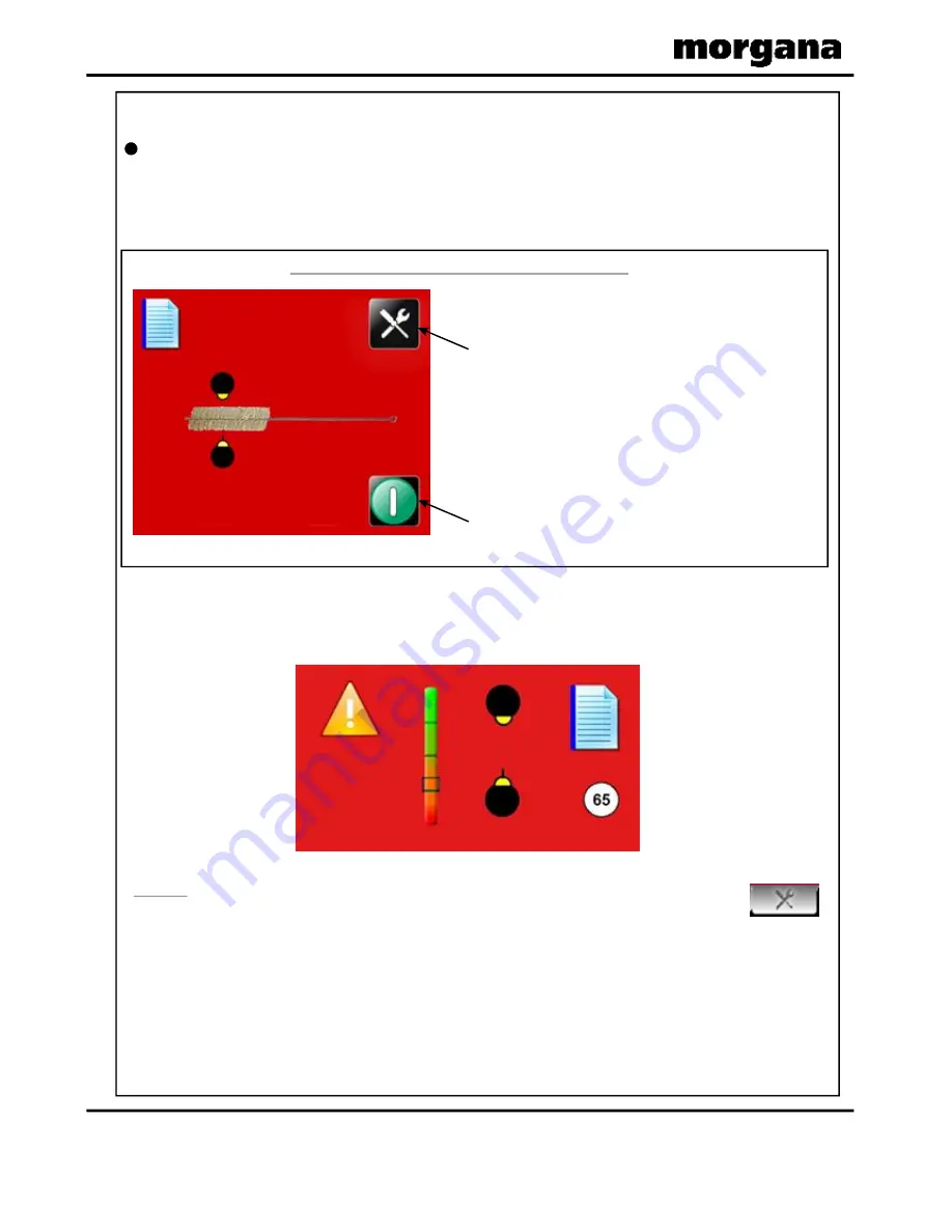
Clean Lead Edge Sensor - Warning Screens.

1. The Clean Lead Edge Sensor warning screen, shown below, will appear when the

Run button is pressed and the strength of the Lead Edge Sensor Beam is at about
50% (i.e. the slider is at about the mid-point position along the Indicator Scale).

2. The Clean Sensor, Error 65 warning screen, shown below, will appear if the strength

of the Lead Edge Sensor Beam is allowed to get down to about 25%. The Lead Edge
Sensors should ideally be cleaned before this warning screen appears.

The Lead Edge Sensors can be cleaned at any time by selecting the Tools Tab
at the bottom of the Touchscreen and cleaning the Sensors as described on Pages 45 &
46.

SENSOR CLEANING WARNING SCREEN

NOTE.

Press the Tools button to clean the
Sensors, as described on Pages 45 & 46.

Press the Run button to ignore the Warning,

and continue running the job.

Summary of Contents for AutoCreaser Pro 33

Page 1: ...SUE 4 JANUARY 2013 DOCUMENT CREASING MACHINE OPERATORS MANUAL 70 171 Morgana Systems Limited United Kingdom Website www morgana co uk Telephone 01908 608888 Facsimile 01908 692399 AutoCreaser Pro 50 CB UL ...

Page 2: ...ting the Stacker unit Equipment spares Setting the machine Setting the blade pressure Setting the blade alignment Installing new blade sets Spares INTRODUCTION THE AUTOCREASER Pro 50 7 QUICK START GUIDE 9 OPERATING THE AUTOCREASER Pro 50 27 29 PAGE 3 SAFETY Do s Don ts 4 6 THE CONTROLS 7 The Morgana AutoCreaser Pro 50 The switch panel Setting the machine Programming the machine Reading stored prog...

Page 3: ...35 4 x 19 7 with Optional extension table Min Sheet Size in automatic mode 210mm x 140mm 8 5 x 5 5 Max Paper Thickness 0 4mm varies according to hardness type of fold and substrate Max No Creases per Sheet 16 Min Distance Between Creases 0 1mm Max No Stored Programmes Unlimited Min Crease Distance from Leading Edge 2 5mm Min Crease Distance from Tail Edge 35mm In Hand Feed Mode up to 2499 9mm to L...

Page 4: ... Do not under any circumstances adjust the paper gate when the machine is switched on REGLES DE SECURITE A FAIRE ET A NE PAS FAIRE Lire ce mode d emploi avant d utiliser la machine Respecter l alimentation électrique indiquée Brancher sur une prise séparée car une surcharge peut entraîner un incendie ou un choc électrique Installer le cordon d alimentation de manière à ne pas pouvoir trébucher par...

Page 5: ...llers Do be aware of low current anti static shock Attention au risque de se coincer les doigts et aux pièces en mouvement lors du fonctionnement de la machine Ne pas porter de vêtements flottants lors de l utilisation de la machine Rassembler les cheveux longs lors de l utilisation de la machine Attention au risque de se coincer les doigts et aux pièces en mouvement lors du fonctionnement de la m...

Page 6: ...ble side lay 13 Switch Panel 2 Stacker assembly 8 Back Stop 14 Fuses 3 Suction slot knob 9 Fixed side lay 15 Gap Set Knob and Lever 4 Touchscreen 10 Roller tilt knob 16 Vacuum Bleed Knob 5 Air separation knob 11 Paper Gate 6 Air distribution knob 12 Exit Guard AUTOCREASER Pro 50 AutoCreaser Pro 50 ...

Page 7: ... and an industry standard Emergency Stop switch which will stop all power going to the machine when activated Features on the Switch Panel System switch Compressor switch When activated the system switch will operate the motors in order to begin the creasing sequence Allows the operator to switch off the compressor unit in order to utilise the machine to manually feed sheets ...

Page 8: ...Page 8 CREASING THE CONTROLS BLANK PAGE ...

Page 9: ...er the system start up procedure the touch screen will be displayed as shown below WARNING Wait at least 10 seconds after making any selection on the Touchscreen panel before switching the machine OFF Failure to do so could result in the data storage being corrupted and the machine not operating AutoCreaser Pro 50 IMPORTANT If you have not been trained to operate this machine we strongly advise th...

Page 10: ...es of any numerical value Fold Selection For quick setting of crease positions on standard size sheets Highlighted fold is type currently selected other folds may be selected Currently selected fold is shown in the status area Page Length On selection the status area is replaced with a calculator for inputting new values Min Length 190mm Vacuum Suck There are two selections available 1 short suck ...

Page 11: ...ng creases will move up by one place You will be asked to confirm deletion of the crease Crease position On selection the status area is replaced with a calculator for inputting new values Plus box for inserting additional creases On selection following creases will move down by one place a maximum number of 6 creases can be seen at any one time further creases can be accessed by use of the scroll...

Page 12: ...Page 12 CREASING Quick Start Guide Creasing turned off Greyed out areas are unselectable Status area willshow creasing is off with red icon ...

Page 13: ...System Switch Not On Push System Switch down to start the machine The machine running screen will appear Click to start machine with settings currently shown you will receive a notification if system switch is not on Press again to stop Job Click to stop machine ...

Page 14: ...and then select the Cover Crease button 3 Select the Crease Settings Tab 4 Enter the Spine Width dimension If necessary adjust the Spine Offset from the centre of the sheet 5 Select the arrow button to set the hinge Dimension Cover Crease button Paper Length Spine Offset Spine Width Arrow Button Hinge Distance ...

Page 15: ...e machine to make the Spine creases 10 Select the arrow button to highlight the Hinge Dimension 11 Run the sheets of paper through the machine to make the Hinge creases TO MAKE THE HINGE CREASES 9 Remove the sheets of paper from the stacker tray and put them back onto the loading table TURN THE SHEETS OVER MAKE SURE THAT THE LEAD EDGE OF THE SHEETS POINT IN THE SAME DIRECTION AS BEFORE Hinge Dimen...

Page 16: ...on if system switch is not on Press again to stop Job Paper length input from the paper setting screen Clicking in this area will take you to the paper setting page Currently selected Vacuum Suck setting for stream setting choose selection 2 Currently selected fold type can be one of the following page Clicking in this area will take you to the Crease setting Clicking in this area will take you to...

Page 17: ...er size Batch size Crease position input calculator input calculator input calculator NOTE The green tick or the red cross must be selected on the Calculator Screen to make the left hand side of the touchscreen active again Pre set Paper sizes for quick insertion Standard sizes for country origin would be shown Pre set Batch sizes for quick insertion ...

Page 18: ...sition TDC Inch paper in direction of arrow to clear jams Main Processor Program version Touch screen software version Machine Speed Adjustment Speed setting 3 will give the fastest throughput of stock through the machine Use speed setting 1 or 2 for troublesome stocks or to synchronise the speed of the AutoCreaser to a Morgana Autofold Pro when they are used together Touch Screen Calibration Chan...

Page 19: ...ting the button at the rear of the housing press this a number of times to obtain the correct orientation required move to the next button to move the position to centralize horizontal 2 i Select the tools menu tab and then Select the Touch Screen calibration icon ii Using a plastic pointer soft leaded pencil biro cap etc and with gentle pressure Touch the centre of the cross in each corner of the...

Page 20: ...ely cause of double sheet feeding This setting is only intended as a guide for instance sheets with an upward curl will require this setting to be increased Setting the Suction Slot The suction slot is located inside the vacuum roller and can be adjusted by releasing and moving the suction knob horizontally in either direction to the required position For light stocks set the knob to the left and ...

Page 21: ... ports Position 2 is recommended for most sheet sizes However a better result may be obtained by using the settings below or by experimentation For sheets longer than A3 17 in order to supply air to the centre of the stack ports 2 3 and 4 open For A5 sheets or 8 inches long ports 1 and 2 open For A4 sheets or 11 inches long ports 1 and 3 open For A3 sheets or 17 inches long ports 1 and 4 open For ...

Page 22: ... driven and supported through the rollers The drive wheels and hubs are fixed to the rollers by means of a grub screw To locate this grub screw the rollers can be rotated by operating the motor manually To operate the motors manually switch the machine on at the Emergency Stop switch Select the Tools tab at the bottom of the touch screen the display will change to that shown below Press the system...

Page 23: ...f stock through the machine 2 When the first crease is less than 37mm from the leading edge of the paper the feed will be noticeably slower when using speeds 2 and 3 3 When the first crease is less than 50mm from the leading edge of the paper the feed will be noticeably slower when using speed 3 NOTES Stream Feed Operating the Autocreaser Pro 50 AutoCreaser Pro 50 Vacuum Suck Select 1 for short su...

Page 24: ...em switch down and then select the left arrow on the touch screen to rotate the rollers in short pulses until the sheet is gripped in the infeed rollers 4 Test the grip of the sheet in the rollers by trying to remove the sheet by hand the sheet should be lightly gripped by the rollers If the grip on the sheet is too light or too heavy it can be adjusted as follows i Turn the gap set locking knob a...

Page 25: ...Page 25 SYSTEM Operating the Autocreaser Pro 50 AutoCreaser Pro 50 ...

Page 26: ...ings Page ii Set the creases as described on pages 11 and 12 6 The job that has been set can now be stored as follows i Select the lower tab or from the status area to get to the Store Settings Page ii The job can be given a name and stored as described below You can also retrieve previously saved jobs modify them or delete jobs that are no longer required Setting the page length Setting the vacuu...

Page 27: ...earch icon this will bring up the search keyboard for text input Search for current jobs to load or modify click save icon to save job to store Delete last character Delete all characters To change your mind return to the previous screen click here Typein job description or first few characters Press search icon to start search To confirm saving of Job click here ...

Page 28: ... confirmation screen Jobs matching characters in text box will be shown in this area selecting job from this area will show job settings in the right hand status area Job selected will be shown in text box Press to load job shown in text box Toggle between search results full list of jobs To cancel overwrite of Job press here To confirm overwrite of Job press here ...

Page 29: ...ng the machine automatically However the paper gate must be raised to its highest position for the sheets to be fed freely Operating the machine in manual sheet feed mode will also require the suction length to be continuous in order to accommodate various types of stock Therefore the feed should be set to Vacuum Drum position 2 see page 10 The machine can now be started by activating the System s...

Page 30: ... left hand extension guide The guides will control the way in which the paper is collated by setting their positions on the stacker bed 2 Place a single sheet from the stack to be creased perforated on to the stacker bed against the fixed left hand guide 3 Position the right hand side guide on to the stacker bed leaving a minimum clearance of approximately 1mm each side of the sheet Setting the St...

Page 31: ... 5mm 5 For shorter sheets the back stop can be used as shown in FIG 13 1 to adjust the position of the paper stack TIPS l l One of the back stops supplied with the machine on the stacker assembly can also be used as a tool holder as demonstrated in the photograph left The scale on the bed can be used to measure the desired creasing or perforating position on the sheet AutoCreaser Pro 50 ...

Page 32: ...ration 56 tooth blades 1 off Set of standard hardened anvils 1 off Perforator stripper 1 off 3mm bondhus wrench allen key 1 off 2mm bondhus wrench allen key The perforator blades are split into two matching halves and are fitted to the drive wheels as shown in the photograph using the four screws supplied A hardened anvil is fitted to the drive hub as shown in the photograph also using the four sc...

Page 33: ... the 2 5mm allen key supplied take one of the matching pairs and mount on to the drive wheel Do not secure the blade 7 Mount the other matching pair to the drive wheel as shown fig 16 1 Secure the blades to the wheel ensuring not to over tighten grub screw 8 Mark on a single sheet the desired perforating position Feed the sheet through the machine manually until the mark can be seen Use this mark ...

Page 34: ... along just enough to clear the hubs They should be mounted as near to the centre of the machine as possible to maximise support The depth of perforation can be adjusted by first loosening the socket set screws in the support block with a 2 5mm allen key Insert the 2 5mm allen key into the grub screw push the allen key up to decrease the perforating depth or down to increase the depth of perforati...

Page 35: ...blade to the Top Dead Centre position 2 Raise the exit guard 3 Using a 6mm allen key unlock the shoulder bolts labelled with scale transfer positioned at each end of the creasing blade 4 Turn the adjustment cam to adjust the blade pressure Increasing the gradient on the scale will increase the blade pressure 5 Ensure that the shoulder bolts are locked after setting The diagram below demonstrates t...

Page 36: ... Remove the stacker unit from the machine 2 Unlock and centralise the roller tilt mechanism in order to locate the heads of the front alignment screws 3 Using a 3mm allen key loosen the cap head type locking screws located on the front face at both ends of the blade anvil as shown below 4 Using a 4mm allen key locate the two front or back alignment screws in the side frame in order to adjust the b...

Page 37: ...ls 70 055 01 70 055 02 into the holes in the adjustment links as shown Push downwards on the handles of the blade extractor tools to release the blade assembly from the power links 5 Slide the blade assembly out of the creasing unit and lay it on a flat surface 6 Slide the adjustment links away from the dowels located in the ends of the blades anvils as shown in the photograph left 7 Place the new...

Page 38: ...22B this can improve the repeatability of the fold relative to the crease for certain fold types or when using lighter stocks Locate the blade extractor tools into the holes in the adjustment links as shown Pull the handles of the blade extractor tools upwards to engage the blade assembly back into the power links 10 Set the cam graphics for both ends of the blade anvil to their lowest point on th...

Page 39: ...et can not be ordered separately ie single blade or anvil The following Blade sets are supplied with the Autocreaser Pro 50 as standard Consisting of a standard blade and anvil blade brushes blade links and alignment bolts Spares kits If the pressure and the alignment of the crease is not to a satisfactory level see pages 33 35 to adjust the creasing line Standard Blade set Part number 76 237 02 P...

Page 40: ... that the emergency stop button has been released Check that the exit guard is down Check that the stacker unit is located correctly and has not been disconnected from the magnetic switch Check that the lower blade anvil is connecting to the home switch mounted below the lower blade anvil Check that the paper stack is not too high or too heavy for the feeder The height of the paper stack should be...

Page 41: ...the exit and remove the blade set see pages 37 39 to access the dual sensor post located in between the drive rollers Using a soft brush clean the visible sensor on the end of the post Use the brush to clean the sensors between the post and the bottom paper guide which are not visible Photograph left shows the dual sensor post containing the sensors If paper gets jammed under the paper gate the va...

Page 42: ...creen this indicates that a paper jam has been detected Press the system switch down and then select the right or left arrows to inch the paper forwards or backwards See page 29 that describes how to remove paper jams Press the green tick button and then press the start button This error message could also mean that the crunch sensors are faulty or need cleaning If the machine stops and error mess...

Page 43: ...a Service Engineer immediately If the machine stops and error message 13 is displayed on the touch screen this indicates that the Lead Edge Sensor has seen a sheet subsequent to the first one as being longer Again this could actually be a longer sheet OR it could be a sensor problem if it is a recurring problem Check that the paper gate has been set correctly If the machine stops and error message...

Page 44: ... Error 65 warning screen shown below will appear if the strength of the Lead Edge Sensor Beam is allowed to get down to about 25 The Lead Edge Sensors should ideally be cleaned before this warning screen appears The Lead Edge Sensors can be cleaned at any time by selecting the Tools Tab at the bottom of the Touchscreen and cleaning the Sensors as described on Pages 45 46 SENSOR CLEANING WARNING SC...

Page 45: ... the strength of the beam The strength of the beam is at its strongest towards the top half of the indicator scale green and at its weakest towards the bottom half of the indicator scale red Note the position of the slider on the indicator scale and then clean the sensors as described on Page 46 This vertical indicator scale is repeated as a horizontal indicator scale on the right hand side of the...

Page 46: ...1 and FIG 2 below Move the brush backwards and forwards several times across the sensors to clean them Note the position of the slider on the indicator scale the slider should have moved nearer to the top of the scale indicating that dust has been removed from the sensors This sensor cleaning operation can be repeated again to see if the sensor beam strength can be further improved The Sensors can...

Page 47: ...sing the cleaning kit provided Cleaning kit part number 90 018 Remove and clean the blade assembly With the blade assembly removed clean the slots and surrounding area within the creasing unit It is recommended that your machine is fully serviced at least once every six months by a factory trained Service Engineer Trouble Shooting AutoCreaser Pro 50 ...

Page 48: ...DUS L WRENCH 4mm 620 020 HEXAGON BALL DRIVER 2 5mm 6 403 01 030 006 409 01 040 004 12 SCREW SOCKET CAP HEAD M3 x 6 LG 1 SCREW SKT SET FLAT PT M4 x 4 LG 1 14 70 055 01 1 BLADE EXTRACTION TOOL OP SIDE 15 70 055 02 1 BLADE EXTRACTION TOOL LAY SIDE 16 08 041 02 1 SLITTING ANVIL UNDERSIZE 1 99 12 1 SLITTER PERF BLADE 28T Page 48 CREASING WARNING THE BLADES FOR ANVIL AND PERFORATING SETS ARE SUPPLIED AS...

Page 49: ...VE BLADE SETS 4 76 237 03 BLADE SET NARROW 5 Page 49 SYSTEM 70 134 ANTI STATIC KIT AUTOCREASER 50 Mk4 6 172 04 01 NARROW SHEET KIT 7 ACCESSORIES OPTIONS May be obtained from May also be obtained and your dealer and fitted to your fitted by your dealer You should machine using the instructions not attempt to fit options as supplied or by reading your specialist tools and knowledge are operators man...

Page 50: ...LADE SET Standard 76 042 DRIVE BELT FEED BED 75 06 02 TOUCHSCREEN ASSY 7 NEW CONTROLLER Page 50 CREASING 75 500 06 MINI ITX MOTHERBOARD A C PRO 50 174 06 01 SMALL STEPPER DRIVER LOW POWER PCB ASSY 174 19 01 RS232 ADAPTOR PCB ASSY 76 156 BLADE POSITION SENSOR LEAD 76 272 PSU ASSEMBLY ATX12V 300W 655 015 PSU UNIT SWITCH MODE 24V 655 016 PSU UNIT SWITCH MODE 48V 76 177 02 INPUT ROLLER Upper 76 019 02...

Page 51: ...bove represent parts which are subject to wear loss or accidental damage and is included for your guidance only Replacement of parts fitted to your machine require specialist knowledge and should therefore be entrusted to your dealer 76 255 LEAD FOLD COMPENSATION SENSOR 75 427 LEAD VALVE SENSOR 609 024 O RING Ø6 x Ø2 5 175 28 01 BUTTERFLY VALVE 76 240 STEPPER DRIVE MOTOR ASSEMBLY 76 241 STEPPER BL...

Page 52: ...OSITION ET CLASSIFICATION DES FUSIBLES T500mAH 250V 681 020 PSUs 24V 48V T4 0AH 250V 681 015 IF FITTED T315mAH 250V 681 011 ANTI STATIC UNIT FUSIBLE PSUs 24 V 48 V FUSIBLE ANTI STATIQUE si installé TRANSFORMER ASSY F15AH 250V 652 047 MAINS IN ...

Page 53: ...ation of this symbol on your equipment is confirmation that you should not dispose of the equipment in the normal household waste stream In accordance with European legislation end of life electrical and electronic equipment subject to disposal must be segregated from household waste Private households within EU Member States may return used electrical and electronic equipment to designated collec...

Page 54: ...t graphics changed to show the Lead Edge Sensor Indicator Bar on all relative pages New pages inserted to describe how to use the Cover Crease Mode for Perfect Bound Covers Pages 14 15 New pages inserted to show the Clean Lead Edge Sensor Warning Screens and how to clean the Lead Edge Sensors Pages 44 to 46 ...

Reviews: