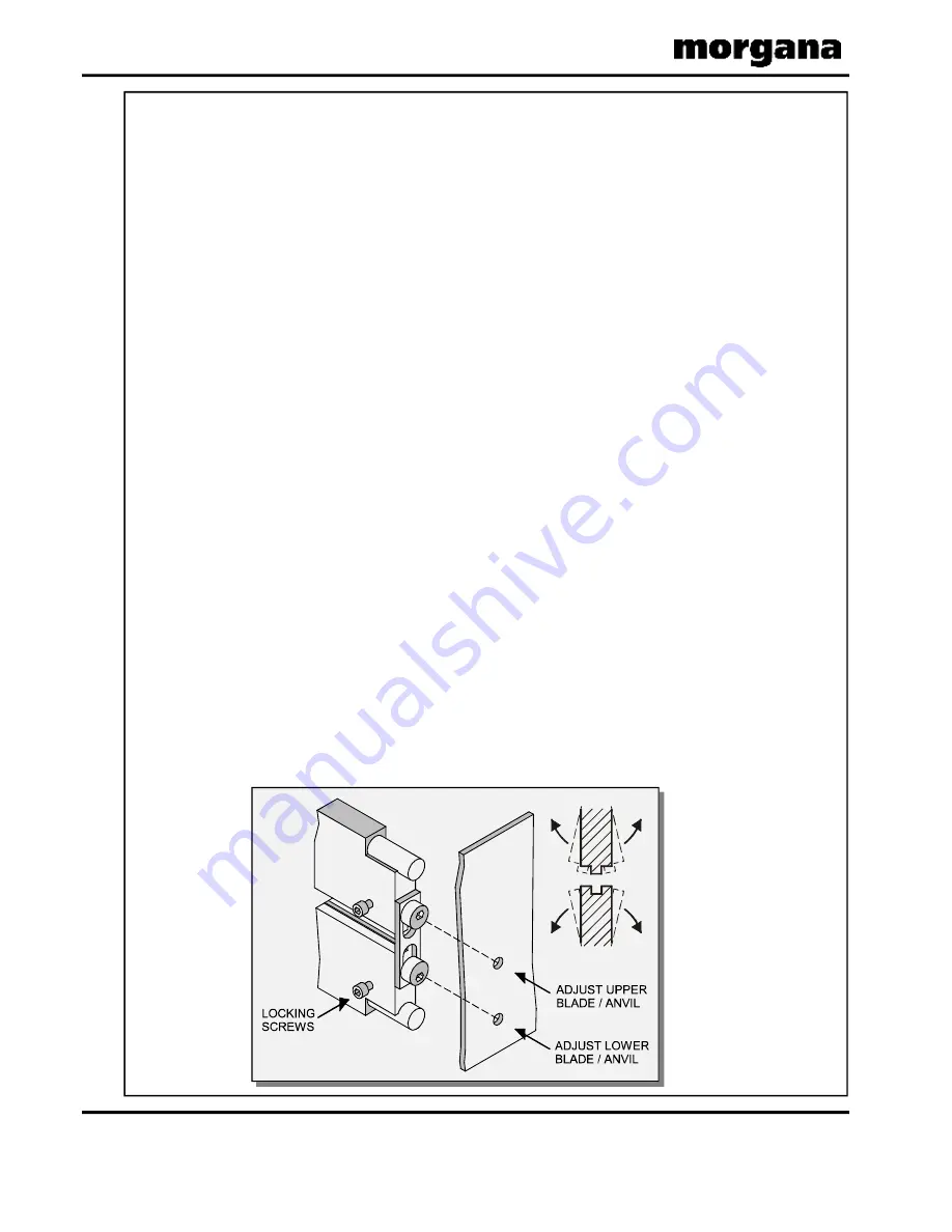
The Blade Assembly
Page 36
CREASING
Adjusting the blade alignment
It is extremely important that the blade and anvil assembly within the creasing unit is
correctly aligned. Misalignment of the blade or anvil can lead to damaged profiles and
subsequently poor quality creasing so it must, therefore, be corrected immediately.
If the blade set is misaligned, the media being driven will be subject to scoring or even
tearing at any point along the crease line.
The below sketch
demonstrates how the blade alignment can be carried out.
Adjustment can be made at either of the blade or anvil. The two clearance holes posi-
tioned above the roller tilt mechanism are the front alignment (one for blade, one for anvil).
The two holes are repeated on the back of the machine for the back alignment.
1. Remove the stacker unit from the machine
2. Unlock and centralise the roller tilt mechanism in order to locate the heads of the
front alignment screws.
3. Using a 3mm allen key, loosen the cap head type locking screws located on the
front face at both ends of the blade /anvil as shown below.
4. Using a 4mm allen key, locate the two front or back alignment screws in the side
frame in order to adjust the blade / anvil.
5. The upper screw of the two, will adjust the upper blade / anvil whereas the
lower screw will adjust the lower blade / anvil both in very small increments.
6. In order to obtain the required position, adjust either the blade or the anvil by a
small amount and then operate the machine to test the form of the crease.
Repeat the exercise until centralisation is located.
7. Using a 3mm allen key, lock the cap head type screws (as per step 3) on both the
upper and lower blade / anvil.
Please note that to avoid damage to the
blade set, adjustment should only be made in small increments.


