Moog PRIZM Mini4 Series User'S Manual And Troubleshooting Manual Download Page 4

Moog Components Group 

Mini4, Rev C 

February 23, 2009


(201580-xxx And 201590-xxx) 


Page  4 of 19 


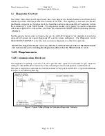
video  analog-to-digital  converters  (ADCs)  and  the  data  interface  chips)  through  a  programmable  logic 
device.   The boards also provide the interface for a daughter board connection.. A block diagram of the 
basic  Mini4  Video  Input  and  Output  Board  I/O  is  shown  on  the  following  page  and  explained  in  the 
subsequent paragraphs. 
 
The transmit portion (uplink from vehicle to surface) of the M4 Video Input board takes in the 4 video 
signals from the ADCs, the 6 onboard serial data signals and the daughter board data and clock signals 
and  converts  them  to  a  single  serial  optical  signal.    The  signal  is  transmitted  to  the  M4  Video  Output 
board at the other end of the fiber optic link in the control/viewing area.  The receive portion of the M4 
Video Output board accepts the optical signal, recovers the 4 video channels, recovers the 6 serial data 
signals and routes them to the appropriate RS-232/RS-485/RS-422 driver chips, and recovers the daughter 
board clock and data signals and routes them to the daughter board connection.    
   
There are no video signals in the optical signal from the Mini4 Video Output board. The transmit portion 
(downlink  from  surface  to  vehicle)  of  the  M4  Video  Output  board  takes  in  the  6  onboard  serial  data 
signals and the daughter board data and clock signals and converts them to a single serial optical signal.  
The  signal  is  transmitted  to  the  M4  Video  Input  board  at  the  other  end  of  the  fiber  optic  link  in  the 
vehicle.  The receive portion of the M4 Video Input board accepts the optical signal, recovers the 6 serial 
data  signals  and  routes  them  to  the  appropriate  RS-232/RS-485/RS-422  driver  chips,  and  recovers  the 
daughter board clock and data signals and routes them to the daughter board connection.    
 
The M4 boards require a +5VDC power source provided  through the 2-pin Phoenix connector at J4.  The 
boards have an on-board 5V to 3.3V and 2.5V converters to provide power for the components that use 
those supply voltage.  


Summary of Contents for PRIZM Mini4 Series

Page 1: ...hooting Guide February 23 2009 Rev C Moog Components Group Springfield Operations 750 West Sproul Road Springfield PA 19064 E Mail mcg moog com URL www moog com components Tel 610 328 4000 Fax 610 605...

Page 2: ...Video Input and Output Board Specifications 14 1 3 4 Mini4 Video Input and Output Board Dimensions 15 1 3 5 Mini4 Video Input and Output Board Power Requirements 15 1 3 6 Power Section Testing 16 1 3...

Page 3: ...llowing printed circuit board PCB revisions PCB Revision A Original design not currently in production PCB Revision B Respin to correct routing not currently in production PCB Revision C Respin to cor...

Page 4: ...rial data signals and routes them to the appropriate RS 232 RS 485 RS 422 driver chips and recovers the daughter board clock and data signals and routes them to the daughter board connection There are...

Page 5: ...indicates the on board 2 5V converter is operational D7 Green Incorrectly labeled 3 3V located on the bottom center of the board When ON indicates that 5V is available to the display LED ribbon heade...

Page 6: ...ta is being transmitted out of the board on channel 6 D21 Green Located on the upper left corner of the board labeled TD ON when RS 485 Diagnostics data is being transmitted out of the board D22 Red G...

Page 7: ...e Video Input board are as follows J2 Daughterboard Connector VDC Supply 1 o o 2 VDC Supply RXD_DB 3 o o 4 TXD_DB GND 5 o o 6 GND RXC_DB 7 o o 8 TXC_DB RCV LINK 9 o o 10 Future J3 Power Diagnostics RT...

Page 8: ...16 T3_LED R4_LED 17 o o 18 T4_LED R5_LED 19 o o 20 T5_LED R6_LED 21 o o 22 T6_LED RDIAG_LED 21 o o 22 TDIAG_LED NOTE J11 header is located at the bottom center side of the board Pin 1 is the upper ri...

Page 9: ...Output Board Indicator and Controls LEDS There are 21 surface mount SMD LED indicators on the Mini4 Video Output board to indicate different statuses that are covered by function below NOTE The LEDs b...

Page 10: ...input signal on video channel 2 When ON indicates that this board has approximately 1 0Vp p input signal either video or analog signal D35 Green Located on the left bottom of the board section labeled...

Page 11: ...reen is ON when serial data is being received into the board on channel 3 Red is ON when serial data is being transmitted out of the board on channel 3 D26 Green Located on the upper left corner of th...

Page 12: ...R6 19 o o 20 T6 R6 21 o o 22 T6 No Connect 23 o o 24 No Connect NOTE J5 header is located at the upper left side of the board Pin 1 is the bottom right pin as identified by a square pad J7 Video Chann...

Page 13: ...are required J12 ISP Header 3 3V 1 o o 2 TMS TCK 3 o o 4 TDI N C 5 o o 6 TDO GND 7 o o 8 NOTE J12 to be used only bye PRIZM JUMPERS There are 6 jumpers on the Mini4 Video Output Board PIN 1 DENOTED B...

Page 14: ...the slew rate limiting on the RS 232 driver chips themselves M4 RS 485 RS 422 Data Channel Selection and Operation The 2 RS 485 RS 422 channels can have several possible configurations The configurat...

Page 15: ...plied via daughter card connector Number of Data Channels Depends on Daughterboard refer to Daughterboard manual Remote LED Status Display Capability J9 ribbon header carries LED status as TTL level s...

Page 16: ...not available replace the board with a spare If 2 5V is available check the display LED D6 If D1 is not on and Daughterboarrd operation is required Verify that either F6 for 3 3VDC to D B or F5 for 5...

Page 17: ...t the video input connector Check the video signal at the connector with a monitor or an oscilloscope If a video signal is present at the Video Input board replace the board with a spare If this does...

Page 18: ...rds to talk to each other in loop back Both RX and TX LEDs on both boards should be lit and or flickering in response to the data traffic If the RS 422 data channel is not operating correctly first ch...

Page 19: ...he use of an RS 485 channel in the multiplexer system for connectivity between the topside Diagnostic PC and the remote multiplexer The Diagnostics for the Mini4 TRANSPARENTLY carries the local and re...

Reviews: