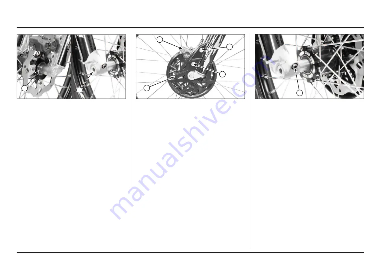
Montesa COTA 301RR 2023 Owner'S Manual Download Page 127

5-2

5-2

Frame servicing

(1) SIDE COLLAR

(2) AXLE

 INSTALLATION

Clean the surfaces where the axle and axle clamps con-

tact each other.

Place the front wheel between the fork legs.

Apply thin layer of grease to the axle surface.

Apply grease to the axle threads.

Install the axle from the right side through the wheel and 

left side collar.

Tighten the axle to the specified torque.

Torque: 69 N•m (7.0 kgf•m, 51 lbf•ft)

(1) BRAKE CALIPER   

(2) DISC COVER

(3) BOLTS

Install the brake caliper, flange collars and disc cover. 

Apply a locking agent to the threads and tighten the mou-

nting bolts to the specified torque.

Torque: 26 N•m (2.7 kgf•m, 20 lbf•ft)

With the front brake applied, pump the fork up and down 

several times to seat the axle and check the front brake 

operation.

(1) AXLE PINCH BOLTS

While keeping the fork parallel, tighten the axle pinch bolt 

to the specified torque.

Torque: 23 N•m (2,3 kgf•m, 17 lbf•ft)

2

1

1

1

2

3

3

Summary of Contents for COTA 301RR 2023

Page 1: ...PGM FI Racing Trial Owner s Manual 2023...

Page 2: ...or others Each safety message is preceded by a safety alert symbol and one of three words DANGER WARNING or CAUTION These signal words mean DANGER You WILL be KILLED or SERIOUSLY HURT if you don t fo...

Page 3: ...Racing version COTA 301RR 4ED Racing version COTA 301RR RACE REPLICA All information in this publication is based on the latest product information available at the time of approval for printing MONTE...

Page 4: ...d on the right side of the steering head The serial number of the engine is stamped on the lower right side of the crankcase MODEL TYPE FRAME No ENGINE No MRT 300 P ED 2ED VTDND15B PE000001 NN4E710000...

Page 5: ...owners manual 2 95 Caution label This motorcycle is not designed to transport a passenger Read owner s manual carefully For yourprotection always wear your helmet while riding Ethanol ethyl alcohol 5...

Page 6: ...Labels ED 2ED 3 2 1 6...

Page 7: ...Labels 3ED 4ED 4 2 1 7 3 5...

Page 8: ...aking any modifications or adding an accessory be sure to read the following information WARNING Improper accessories or modifications can cause a crash in which you can be seriously hurt or killed Fo...

Page 9: ...ine Removal Installation 4 18 Cylinder Compression 4 20 Cylinder Head Removal 4 23 Cylinder Head Disassembly 4 25 Cylinder Head Inspection 4 26 Valve Guide Replacement 4 27 Valve Seat Inspection Refac...

Page 10: ...ts well ahead of the season page 3 2 To The New Owner By selecting a MONTESA COTA 301RR as your new machine you have placed yourself in a distinguished family of owners and riders The COTA is a high p...

Page 11: ...Memo Memo...

Page 12: ...tructions Operation component locations ED 2ED magnetic stop switch kickstarter rear brake pedal clutch lever front brake lever throttle grip rearview mirror rearview mirror shift lever light control...

Page 13: ...Operating instructions 1 2 1 2 Operation component locations 3ED 4ED magnetic stop switch throttle grip front brake lever clutch lever shift lever kickstarter rear brake pedal mapping switch...

Page 14: ...istilled Water WARNING Removing the radiator cap while the engine is hot will allow the coolant to spray out seriously scalding you Always let the engine and radiator cool down before removing the rad...

Page 15: ...motorcycle 20 minutes observing the same cautions as for a new motorcycle y When the piston piston ring gears etc are replaced they must be broken in observing the first 30 minutes using not more tha...

Page 16: ...m km h to mph and vice versa depending on their initial setting 1 SPEEDOMETER 2 ODOMETER 3 CLOCK 4 RIDE TIME 5 TURN SIGNAL INDICATOR 6 HIGH BEAM INDICATOR 7 MALFUNCTION INDICATOR LAMP MIL Odometer Spe...

Page 17: ...will increase by one minute each time the button is pressed y Keep the button pressed the minute digit advan ces fast Release the button when the desired minute is displayed 3 Press the MODE SET butt...

Page 18: ...rom neutral down to first gear 4 Release the front brake lever Gradually open the throttle while you slowly release the clutch lever If the engine min 1 rpm speed is too low when you release the clutc...

Page 19: ...heels to slip Any wheel slip will reduce your control of your Cota When riding in wet or raining conditions or on loose sur faces the ability to maneuver and stop will be reduced All of your actions s...

Page 20: ...ter cylinder piston below 0 5 mm 0 019 in Clutch Lever Free Play Standard cluth lever free play should be between 0 5 15 mm 0 019 0 60 in NOTICE Do not adjust the free play of the lever to less than...

Page 21: ...orn 1 HEADLIGHT DIMMER SWITCH 1 TURN SIGNAL SWITCH Headlight dimmer switch Turn the dimmer switch to to select high beam or to to select low beam Turn signal switch Move to to signal a left turn to si...

Page 22: ...justed by turning the adjuster Free play must be adjusted to provide 0 5 1 5 mm 0 019 0 060 in clearance between the end of the ad juster and the front brake master cylinder piston y To reduce free pl...

Page 23: ...ticular body size or riding style Each of the ergonomic dimensions of the motorcycle were determined to suit the greatest possible number of riders based on an average size rider 1 LOCK NUT 2 ROD 3 AD...

Page 24: ...le cylinder 3 5 inclined from vertical Bore and stroke 81 5 x 57 2 mm Displacement 298 cm3 Compression ratio 10 4 1 Valve timing Intake valve opens Intake valve closes Exhaust valve opens Exhaust valv...

Page 25: ...xture coolant and distilled water Radiator cap relief pressure 108 kPa 1 1 kgf cm2 Presi n de alivio tap n del radiador 108 kPa 1 1 kgf cm2 Unit mm in Item Standard Service limit Cylinder Head Valves...

Page 26: ...0 652 17 06 0 672 16 97 0 668 Unit mm in Unit mm in Item Standard Service limit Crankshaft Transmission Crankshaft runout Right Left 0 03 0 001 0 05 0 002 Connecting rod big end Side clearance Radial...

Page 27: ...or resistance 13 5 14 5 V 1 800 min 1 rpm 0 7 1 0 20 C 2 3 2 6 k 20 C Bulbs Headlight Position light Brake tail light Turn signal light Speedometer 12V 35 35 W 12V 4 W 12V 21 5 W 12V 10 W X 4 12V Unit...

Page 28: ...oil bleeder screw 1 8 6 0 6 4 3 Clutch spring bolt 6 6 12 1 2 9 Clutch center lock nut 1 18 69 7 0 51 Note 1 Drive sprocket UBS bolt 1 8 31 3 2 23 Shift drum center special bolt 1 8 22 2 2 16 Note 4...

Page 29: ...ront axle 1 17 69 7 0 51 Note 1 Rear axle nut 1 17 69 7 0 51 Note 1 Final driven sprocket nut 4 8 32 5 3 3 23 9 Shock absorber Upper mounting bolt nut Lower mounting bolt nut 1 1 10 10 39 4 0 29 39 4...

Page 30: ...diagnosis system Diagnostic tool DST Generic tool PGM FI Self diagnosis system Description Tool number Applicability Spoke nipple wrench 07701 0020300 Front spoke nipple Gear holder 07724 0010100 Pri...

Page 31: ...kcase inside engine oil Repsol 4T stroke engine oil 10W 30 or equivalent 600 cm3 Item Material Remarks Connecting rod small end I D Molybdenum oil solution A 50 50 mixture of molybdenum disulfide grea...

Page 32: ...tipurpose grease Each oil seal lips Water seal lips Right crankcase and cylinder head cover water hose joint thread Sealant Cylinder head cover mating surface Three Bond 1207B or equivalent Cam chain...

Page 33: ...ner roller bearings Clutch lever pivot sliding surface Front and rear wheel axle thread Step joint pin surface Throttle pipe sliding surface and throttle wire drum 4 stroke engine oil Brake hydraulic...

Page 34: ...Service data 2 11 2 11 Cable Harness Routing ED 2ED 1 FRONT BRAKE HOSE 2 THROTTLE CABLE 3 CLUTCH HOSE 4 MAGNETIC STOP SWITCH CONNECTOR 45 2 1 4 3 FRONT FRONT...

Page 35: ...Service data 2 12 2 12 Cable Harness Routing 3ED 4ED 1 FRONT BRAKE HOSE 2 THROTTLE CABLE 3 CLUTCH HOSE 4 MAGNETIC STOP SWITCH CONNECTOR 5 MAPPING SWITCH FRONT FRONT 15 mm 5 90 2 1 3 4...

Page 36: ...TOR SUB INSTALLATION 8 6P CONNECTOR SPEEDOMETER 9 3P CONNECTOR SPEED SENSOR 10 4P CONNECTOR MIL 11 FRONT STOP SWITCH CONNECTOR 12 2P CONNECTOR INACTIVE 13 9P CONNECTOR LIGHTING SWITCH 14 INDICATOR LIG...

Page 37: ...BREATHER HOSE 4 AIR FILTER BOX BREATHER HOSE 5 STORAGE TANK 6 ENGINE STOP SWITCH WIRE 7 FAN MOTOR WIRE 8 FUEL CAP BREATHER HOSE 9 SPARK PLUG WIRE 10 WIRE HARNESS TO IGNITION COIL 11 ECT SENSOR 12 FUEL...

Page 38: ...S BOOT FAN MOTOR 2P CONNECTOR POWER MAPPING 4P CONNECTOR COOLANT TEMPERATURE 2P CONNECTOR ED 2ED 5 UPPER RADIATOR HOSE 6 SPARK PLUG WIRE 7 FAN MOTOR WIRE 8 FILTER BOX BREATHER HOSE 9 CYLINDER HEAD BRE...

Page 39: ...Service data 2 16 2 16 1 THROTTLE CABLE 2 CLUTCH HOSE 3 FUEL TANK BREATHER HOSE 1 2 3 2 3 1 45 FR FR UPPER UPPER FR RH RH RH RH RH...

Page 40: ...HOSE 3 FILTER BOX BREATHER HOSE 4 ALTERNATOR WIRE 5 CONDENSER 2P BLACK CONNECTOR 6 REGULATOR RECTIFIER 5P BLACK CONNECTOR 7 BANK ANGLE SENSOR 8 FAN MOTOR RELAY 9 REAR BRAKE RESERVOIR TANK 10 SPEED SEN...

Page 41: ...AIR FILTER BOX BREATHER HOSE 5 TRANSMISSION BREAHTER HOSE 6 WIRE HARNESS 7 FUEL FEED HOSE 8 REGULATOR RECTIFIER 5P BLACK CONNECTOR 9 CONDENSOR 10 CONDENSOR 2P BLACK CONNECTOR 11 BANK ANGLE SENSOR 12 F...

Page 42: ...Service data 2 19 2 19 1 REAR BRAKE HOSE 2 REAR BRAKE RESERVOIR HOSE 3 SPEED SENSOR ED 2ED 90 UPPER UPPER RH FR FR RH 1 2 3...

Page 43: ...Service data 2 20 2 20 1 FUEL FEED HOSE 2 TRANSMISSION BREATHER HOSE 1 2...

Page 44: ...amage or wear y Loose bolts screws and other fasteners 3 Service and maintenance Maintenance schedule Perform pre ride Inspection at each scheduled maintenance period I Inspect and clean Adjust Lubric...

Page 45: ...et Wear or damage Frame Front rear tire Wear Brake pad Wear Chain slider Wear Driven sprocket Wear or damage Drive chain Elongation or wear Warming up Inspection When warming up the engine check for t...

Page 46: ...the air cleaner element A fire or explosion could result Soak the element in engine oil and squeeze out the excess NOTICE Do not twist the element to squeeze out the excess Failure to follow this pre...

Page 47: ...plug and the cap Spark Plug Cap Remove the spark plug cap from the spark plug Clean the inside of the plug cap with electrical contact cleaner to prevent misfire 1 INSULATOR Spark Plug Using a spark p...

Page 48: ...alve stem and measure the intake and exhaust valve clearances Valve clearance Intake 0 12 0 03 mm 0 005 0 001 in Exhaust 0 30 0 03 mm 0 012 0 001 in Adjust by loosening the lock nut and turning the ad...

Page 49: ...oil filler hole Specified engine oil Repsol 4 stroke motorcycle oil SAE 10W 30 or equivalent Capacity 0 41 liter 0 43 US qt 0 36 Imp qt after draining 0 44 liter 0 46 US qt 0 39 Imp qt after oil filt...

Page 50: ...he oil filter cover into the left crankcase while aligning the cover flange with the oil filter groove Make sure that the oil filter cover seats properly in the crankcase Install the retaining plate a...

Page 51: ...ght position on level surface 2 Remove the oil filler cap from the clutch cover 3 Place an oil drain pan under the engine to catch the oil then remove the drain bolt and sealing washer from the left c...

Page 52: ...is damaged Replace the water seal or the oil seal page 4 15 Coolant Replacement WARNING Removing the radiator cap while the engine is hot will allow the coolant to spray out seriously scalding you Al...

Page 53: ...properly or the lever feels soft or spongy bleed the air from the system 2 Remove the reservoir cover and diaphragm check the clutch fluid level If the level is low inspect the clutch hose and fittin...

Page 54: ...ck the drive chain slack and free wheel rotation After adjustment tighten the axle nut to the specified torque Torque 69 N m 7 0 kgf m 51 lbf ft Lubricate the drive chain Hook the drive chain tensione...

Page 55: ...slack page 3 11 1 BOLTS NUT 2 DRIVEN SPROCKET Install the drive sprocket onto the countershaft as shown Install the spring washer and bolt then tighten the bolt to the specified torque Torque 31 N m...

Page 56: ...OT 4 only 1 COVER 2 MIN LEVEL Check that the brake hose do not bind or kink in all steering position and is not pulled when the suspension is extended Replace the brake fluid every 6 months Replace th...

Page 57: ...o wobble right and left 1 BRAKE DISC 2 DISC BOLT 3 COLLAR Brake System Refer to page 1 11 for Brake Lever Adjustment Refer to page 1 12 for Brake Pedal Height Adjustment Brake Discs Measure the rear b...

Page 58: ...ar 2 3 N m 0 2 0 3 kgf m 1 5 2 2 lbf ft Rim lock nut 13 N m 1 3 kgf m 9 lbf ft 1 SPOKE 2 SPOKE NIPPLE 3 RIM LOCK Steering Head Bearings Support the motorcycle using the maintenance stand with its fron...

Page 59: ...xtends y Compression damping right fork Turning the compression damping adjuster adjusts how quickly the fork compressed y Spring pre load left fork Turning the spring pre load adjuster adjusts the sp...

Page 60: ...er should always be adjusted for the rider s weight and track conditions by using one or more of the following methods y Spring pre load Turning the spring pre load adjuster adjusts the spring initial...

Page 61: ...before carrying out any maintenance work 1 DUST COVER 2 BULB PAWL 3 BULB 4 CONNECTORS Remove the housing for the upper headlight Disconnect the connectors Remove the dust cover Unhook the bulb pawl R...

Page 62: ...fue ling Stop engine and keep heat sparks and flame away Drain or refuel only outdoors Wipe up spills immediately 3 Remove the coolant drain bolt at the water pump cover to drain coolant Drain coolant...

Page 63: ...3 20 3 20 Memo...

Page 64: ...VALVE 2 SNAP RING Check the relief valve operation by pushing the relief valve piston Installation Apply oil to a new O ring and install it onto the relief valve groove Install the relief valve into t...

Page 65: ...WAY REED VALVE Inspection Check the oil pump driven gear for wear or damage Check the oil pump shaft for wear or damage Check the one way reed valve for damage replace if necessary Check the oil pump...

Page 66: ...everse order of removal 1 OIL PUMP SHAFT 2 INNER ROTOR 3 FLAT SURFACES 4 OUTER ROTOR Assembly Apply clean engine oil to the oil pump rotors and shaft Install the oil pump shaft into the right crankcas...

Page 67: ...irty and clean if ne cessary Cover the fast connector with a cloth 3 Hold fast connector with one hand and tighten the two pins of the pawl with the other hand while pulling the connector backwards Di...

Page 68: ...flame away y Refuel only outdoors y Wipe up spills immediately NOTICE y Before disconnecting the fuel hoses release the fuel pressure by loosening the fuel feed hose banjo bolt at the injector holder...

Page 69: ...to the fuel pump 2P connector terminals check amount of fuel flow for 10 seconds Amount of flow 0 749 l min 125 cm3 minumun 10 seg If the fuel flow is less than specified inspect the following Pinched...

Page 70: ...ct the fuel tank breather hose Remove the fuel tank mounting bolts Pull up the fuel tank and disconnect the fuel pump 2P connector Remove the fuel tank and injector as an assembly being careful not to...

Page 71: ...removed Clean any oil off from the mating surface of the fuel pump base and fuel tank Install a new packing onto the fuel pump base Install the fuel pump assembly into the fuel tank as pictures shows...

Page 72: ...t to pinch the throttle cable Install and tighten the fuel tank mounting bolts Connect the fuel tank breather hose to the hose clip 1 FUEL TANK 2 BOLT 3 BREATHER HOSE 1 2P CONNECTOR Always replace the...

Page 73: ...engine filter system from the pump body 1 PAWL 2 PUMP BODY 3 PUMP 1 FUEL PUMP Remove the fuel tank Remove the bolts from the fuel pump base and remove the base Take the fuel pump out of the fuel tank...

Page 74: ...earing is properly positioned and sup ported in the fuel tank 1 PUMP 3 PAWLS 2 BODY 4 CONNECTING PIPE 1 BEARINGS 2 PUMP 3 ENGINE CABLES 4 MOTOR 5 BODY Replace the bearings with new ones every time the...

Page 75: ...s position as shown Tighten the pump mounting bolts in alphabetical order as shown in the image Torque 7 9 N m 0 7 0 9 kgf m 5 1 6 6 lbf ft Mount the tank on the chassis Connect the breather hose to t...

Page 76: ...from the housing joint 1 BOLTS NUTS 2 AIR CLEANER HOUSING Removal Installation Do not remove the injector from the injector holder Replace the injector and holder as an assembly Always replace the O...

Page 77: ...le end from the throttle drum Loosen the insulator clamp screw then remove the insulator from the throttle body Installation Install the insulator onto the throttle body while aligning its slit with t...

Page 78: ...eplacement Drain the transmission oil page 3 8 Remove the following Water pump cover bolt cover dowel pins O ring Right crankcase cover and washer page 4 40 Hold the water pump gear teeth using a suit...

Page 79: ...into the right crankcase cover Hold the water pump gear using a suitable tool and tighten the impeller to the specified torque Torque 12 N m 1 2 kgf m 9 lbf ft Install the washer and right crankcase c...

Page 80: ...the ground eyelet bolt Remove the ignition coil mounting bolt Remove the spark plug wire wire harness breather hose clamp Disconnect the ECT sensor 3P Gray connector 1 GROUND EYELET 2 BOLTS 3 IGNITION...

Page 81: ...e engine removal for servicing Crankshaft Oil pump Shift forks and shift drum Transmission Cylinder piston 1 IGNITION COIL 2 BOLTS 3 GROUND EYELET 4 WIRE CLAMP Installation is in the reverse order of...

Page 82: ...ion 24 N m 2 4 kgf m 17 8 lbf ft 24 N m 2 4 kgf m 17 8 lbf ft 26 N m 2 6 kgf m 19 2 lbf ft 26 N m 2 6 kgf m 19 2 lbf ft 69 N m 6 9 kgf m 50 9 lbf ft 39 N m 4 0 kgf m 28 7 lbf ft 50 N m 5 1 kgf m 36 8...

Page 83: ...stopper tool This tool can be easily be made from a thin 1 mm thick piece of steel as shown 1 SEALING BOLT WASHER 2 STOPPER TOOL 1 CYLINDER COMPRESSION GAUGE Cylinder Compression Warm up the engine to...

Page 84: ...ylinder head side cap Remove the camshaft bearing retainer from the cylinder head cover 1 BOLTS SEALING WASHERS 2 SH BOLTS 3 SEALING WASHERS 4 CYLINDER HEAD COVER 1 BOLTS 2 TAPPET ADJUSTING HOLE COVER...

Page 85: ...wear or damage If any components are faulty replace the camshaft assembly 1 BEARINGS 2 CAMSHAFT 1 INTAKE ROCKER ARM SHAFT 2 EXHAUST ROCKER ARM SHAFT 3 INTAKE ROCKER ARM 4 EXHAUST ROCKER ARM Disassembl...

Page 86: ...ttern in two or three steps Remove the nuts washers and cylinder head 1 BOLTS 2 NUTS WASHERS 3 CYLINDER HEAD Cylinder Head Removal Remove the following Exhaust pipe Throttle body insulator Cylinder he...

Page 87: ...T COLLAR 3 CAM CHAIN TENSIONER 4 PIVOT BOLT 5 APPLY LOCKING AGENT Inspection Inspect the cam chain tensioner and cam chain guide for excessive wear or damage replace if necessary 1 CAM CHAIN TENSIONER...

Page 88: ...not compress the valve springs more than necessary to remove the cotters Tools Valve spring compressor 07757 0010000 Compressor attachment 07959 KM30101 1 VALVE SPRING COMPRESSOR 2 ATTACHMENT 3 COTTER...

Page 89: ...the free length of the intake and exhaust valve springs Service limits Inner 24 9 mm 0 98 in Outer 27 6 mm 1 09 in 1 OUTER VALVE SPRING 2 INNER VALVE SPRING Cylinder Head Inspection Cylinder Head Rem...

Page 90: ...ide I D using a ball gauge or inside micrometer Service limit IN EX 4 552 mm 0 1792 in Subtract each valve stem O D from the corresponding guide I D to obtain the stem to guide clearance Standard IN 0...

Page 91: ...DTH Check that the valve guides are at the proper depth using a slide caliper adjust the height if necessary Specified depth IN 8 0 8 3 mm 0 31 0 33 in EX 8 2 8 5 mm 0 32 0 33 in Let the cylinder head...

Page 92: ...erior cutter Valve Seat Refacing Valve seat cutters grinders or equivalent valve seat refacing equipment are recommended to correct worn valve seat Follow the refacing manufacturer s instructions y Co...

Page 93: ...the existing valve seat material Tools Flat cutter 25 mm 07780 0012000 Flat cutter 21 5 mm 07780 0012800 Cutter holder 4 5 mm 07781 0010600 or equivalent commercially available Use a 45 cutter remove...

Page 94: ...while turning it slowly to avoid damage to the stem seal Using a 45 seat cutter cut the seat to proper width Make sure all pitting and irregularities are removed Refinish if necessary After refacing w...

Page 95: ...pring compressor 07757 0010000 Compressor attachment 07959 KM30101 To prevent loss of tension do not compress the valve springs more than necessary Tap the valve stems gently with two plastic hammers...

Page 96: ...kcase Remove the piston pin clips with pliers Press the piston pin out of the piston and remove the piston Spread the piston rings and remove them by lifting up at a point just opposite the gap Piston...

Page 97: ...it Taper 0 05 mm 0 002 in Out of round 0 05 mm 0 002 in Inspect the top of the cylinder for warpage Service limit 0 05 mm 0 002 in Piston Piston Ring Remove the carbon deposits from the piston head or...

Page 98: ...piston pin O D Service limit 15 98 mm 0 629 in Replace the piston pin if necessary Calculate the piston pin to piston clearance Service limit 0 04 mm 0 002 in Insert each piston ring into the cylinder...

Page 99: ...pushed When it is turned clockwise with a screwdriver the tensioner shaft should be pulled into the body The shaft should spring out of the body as soon as the screwdriver is released Piston Installat...

Page 100: ...in 2 3 steps to the specified torque Torque 39 N m 4 0 kgf m 29 lbf ft 1 DOWEL PINS 2 NEW GASKET Apply locking agent to the cylinder mounting sealing bolt threads Install the cylinder mounting sealing...

Page 101: ...e hanger bolt tighten the nut to the specified torque Torque 24 N m 2 4 kgf m 17 lbf ft Connect the radiator hose to the water joint tighten the clamp screw securely Install the following Camshaft Cyl...

Page 102: ...rocker arm shaft groove Place the intake rocker and exhaust rocker arm into the cylinder head cover The intake rocker arm is identified with groove on the end of the shaft Install the intake and exhau...

Page 103: ...T ADJUSTING HOLE CAP 3 BOLTS Check the valve clearance page 3 4 Install new O rings into the tappet adjusting hole cover grooves Install the tappet adjusting hole cap with their UP marks facing up Ins...

Page 104: ...tern in 2 3 steps Install the kickstarter pedal and tighten the bolt to the specified torque Torque 37 N m 3 8 kgf m 27 4 lbf ft Connect the lower radiator hose Fill the crankcase with recommended tra...

Page 105: ...brake fluid Apply silicone grease to the O rings Install 23 x 2 1 mm O ring Black into the spring side groove Install 21 8 x 2 4 mm O ring Green into the lifter plate side groove Do not interchange t...

Page 106: ...HOLDER 1 CLUTCH CENTER 2 CLUTCH DISCS 3 CLUTCH PLATE 4 PRESSURE PLATE 5 PAPER DISCS 1 LOCK WASHER 2 PLAIN WASHER 3 SPRING BASE WASHER Hold the clutch assembly with the clutch center holder and remove...

Page 107: ...sure plate for wear or damage y Mainshaft O D at clutch outer guide 1 LIFTER PIECE ASSEMBLY 1 OUTER GUIDE 2 NEEDLE BEARING 1 CIRCLIP 2 THRUST WASHER 3 THRUST NEEDLE BEARING 4 LIFTER PIECE Check the li...

Page 108: ...clutch plates with clean transmission oil Install the clutch discs and plates alternately onto the clutch center starting with the clutch disc Install the clutch pressure plate onto the clutch center...

Page 109: ...O D y Idle gear I D and bushing O D and I D y Countershaft O D at the idle gear bushing 1 RATCHET SPRING 2 STARTER RATCHET 3 PINION GEAR 4 SPINDLE 5 RETURN SPRING 6 COLLAR 1 RETURN SPRING 2 COLLAR 3 W...

Page 110: ...rshaft Note the direction of the idle gear as shown in the illustration Gearshift Linkage Removal Remove the gearshift pedal Pull out the gearshift spindle from the crankcase Remove the guide plate bo...

Page 111: ...EL PIN 6 CUT OUT Install the return spring plain washer and stopper arm and tighten the stopper arm bolt to the specified torque Torque 12 N m 1 2 kgf m 9 lbf ft Install the dowel pin into the shift d...

Page 112: ...Left Crankcase Cover Removal Remove the skid plate and drain engine oil Disconnect the alternator 3P Natural connector and ignition pulse generator 2P Natural connectors Remove the gearshift pedal 1...

Page 113: ...edle bearing using the special tools Tools Bearing remover shaft 15 mm 07936 KC10100 Bearing remover head 15 mm 07936 KC10200 Remover weight 07741 0010201 1 SNAP RING 2 WASHER 3 OIL SEAL 4 NEEDLE BEAR...

Page 114: ...hreads Install the alternator wire clamp Install the stator and ignition pulse generator mounting bolts Tighten the stator mounting bolts to the specified torque Torque 5 4 N m 0 55 kgf m 4 0 lbf ft T...

Page 115: ...evel Install the slid plate 1 3P NATURAL CONNECTOR 2 2P NATURAL CONNECTOR Install the left crankcase cover being careful not to damage the oil filter cover O ring NOTICE The left crankcase cover stato...

Page 116: ...se cover page 4 50 Install the flywheel onto the crankshaft Apply oil to the flywheel nut threads and seating surface Install the washer and flywheel nut 1 WASHER 2 FLYWHEEL NUT 3 APPLY OIL 1 WOODRUFF...

Page 117: ...r 1 OIL PUMP DRIVEN GEAR 2 DRIVE PIN Remove the countershaft collar and O ring Remove the oil pump driven gear and drive pin 1 COUNTERSHAFT COLLAR 2 O RING 1 DRIVE SPROCKET 2 UNIVERSAL HOLDER 3 BOLT 4...

Page 118: ...Place the right crankcase facing down and remove the left crankcase from the right crankcase Remove the gasket and dowel pins Remove the one way reed valve Remove the oil pump shaft oil pump inner and...

Page 119: ...Inspect each part for wear or damage Check the following items specifications page 2 1 y Spinning gear I D y Bushing I D and O D y Mainshaft and countershaft O D y Shift fork I D and claw thickness y...

Page 120: ...LEFT CRANKSHAFT OIL SEAL 6 LEFT CRANKSHAFT BEARING 7 RIGHT CRANKSHAFT BEARING 8 RIGHT CRANKSHAFT OIL SEAL 9 RIGHT MAINSHAFT BEARING 10 RIGHT COUNTERSHAFT BEARING 11 RIGHT SHIFT DRUM BEARING A 1 mm B 0...

Page 121: ...4 58 4 58 Engine servicing Transmission Assembly 1 M2 13T 2 M4 28T 3 M3 15T 4 M5 22T 5 MAINSHAFT M1 15T 6 C2 31T 7 C4 28T 8 C3 30T 9 C5 22T 10 C1 42T 11 COUNTERSHAFT 11 10 9 8 7 6 4 3 2 1 5...

Page 122: ...into the right crankcase Install the mainshaft and countershaft as an assembly into the right crankcase Install the center shift fork with its identification mark facing in Install the right and left...

Page 123: ...IVE GEAR 2 WASHER 3 SPECIAL BOLT Install the primary drive gear collar onto the crankshaft Install the primary drive gear with its groove side facing out Apply oil to the primary drive gear special bo...

Page 124: ...r tighten the special bolt to the specified torque Torque 31 N m 3 2 kgf m 23 lbf ft Install the removed parts in the reverse order of removal 1 NEW O RING 2 COUNTERSHAFT COLLAR Install the drive pin...

Page 125: ...4 62 4 62 Memo...

Page 126: ...ads and clean a contaminated disc with a high quality brake degreasing agent 1 BRAKE DISC 2 COLLAR 3 DISC BOLT 4 LEFT WHEEL BEARING 5 DISTANCE COLLAR 6 RIGHT WHEEL BEARING A 25 1 MM Spokes Check spoke...

Page 127: ...the specified torque Torque 69 N m 7 0 kgf m 51 lbf ft 1 BRAKE CALIPER 2 DISC COVER 3 BOLTS Install the brake caliper flange collars and disc cover Apply a locking agent to the threads and tighten the...

Page 128: ...ork tube down and out 1 FORK BOLT 2 FORK LEG Right Fork Disassembly Before disassembling the fork clean the entire sliding sur face and the bottom of the fork slider Be careful not to scratch the fork...

Page 129: ...e the center bolt and sealing washer Tool Fork damper holder Generic tool 1 FORK DAMPER 2 CENTERING PLATE 3 FORK TUBE Remove the fork damper assembly and centering plate from the fork tube 1 DUST SEAL...

Page 130: ...Right Fork Inspection Check the following items page 2 4 Fork tube for score marks scratches and excessive wear Fork tube runout Fork slider for damage or deformation Fork damper for damage Bushing Ba...

Page 131: ...DRIVER 1 GUIDE BUSHING 4 STOP RING 2 BUCK UP RING 5 DUST SEAL 3 OIL SEAL Using the special tool drive the guide bushing and backup ring until the stop ring groove is fully stuck in the fork slider ba...

Page 132: ...ur recommended fork fluid in the fork leg Specified fork fluid Showa SS05 SAE 5W or equivalent Bleed the air as follows 1 Extend the fork Cover the top of the fork tube with your hand and compress the...

Page 133: ...k tube A scratched fork tube will damage the seal causing an oil leak The fork bolt under spring pressure Before removing the fork bolt turn the pre load adjuster softest position Remove the fork bolt...

Page 134: ...de fork slider for damage or deformation Fork tube runout Fork spring free length Fork tube for score marks scratches and excessive wear Bushing back up ring page 5 5 Fork piston ring for wear or dama...

Page 135: ...rocedure as the right fork page 5 6 Fork tube bushing Guide bushing Back up ring Using the special tool drive the guide bushing and backup ring until the stop ring groove is fully stuck in the fork sl...

Page 136: ...top clamp The fork tubes should be in the first slot related top clamp 1 BOTTOM BRIDGE PINCH BOLTS 2 FORK BOLT 3 TOP BRIDGE PINCH BOLTS Tighten the bottom bridge pinch bolts to the specified torque To...

Page 137: ...1 ADJUSTING NUT 1 DUST SEAL 2 UPPER BEARING 3 STEERING STEM Remove the stem bearing adjusting nut Remove the following Dust seal Upper bearing Steering stem lower bearing 1 STEM 2 LOWER BEARING 3 DUST...

Page 138: ...and driver Tool Steering stem driver Generic tool 1 DRIVER 2 ATTACHMENT 1 STEM 2 UPPER BEARING 3 DUST SEAL Install new bearing races Tools Driver 07749 0010000 Attachment 42 x 47 mm 07746 0010300 Pac...

Page 139: ...ut to the specified torque Torque 99 N m 10 kg m 65 lbf ft Recheck the steering stem adjustment before installing the removed parts 1 ADJUSTER 2 AXLE Rear Wheel Removal Raise the rear wheel off the gr...

Page 140: ...T NUT 3 LEFT WHEEL BEARING 4 DISTANCE COLLAR 5 RIGHT WHEEL BEARING 6 DISC BOLT 7 BRAKE DISC 8 REAR WHEEL NIPPLE A 30 0 5 MM 1 AXLE 2 ADJUSTERS Installation Install the rear brake caliper aligning with...

Page 141: ...nd of the clip in the direction of wheel rotation Check and adjust the drive chain slack page 3 11 Tighten the axle nut Torque 69 N m 7 0 kgf m 51 lbf ft 1 SPRING COMPRESSOR 2 ATTACHMENT 3 SPRING SEAT...

Page 142: ...the collars and dust seals Check the spherical bearing for smooth rotation or da mage Remove the stop ring Press the spherical bearing out using the special tool Tool Spherical bearing driver 07HMF K...

Page 143: ...ing the lower mount then install the lower mounting bolt from the right side Install and tighten the upper and lower mounting nuts to the specified torque Torque Upper mounting bolt 39 N m 4 0 kgf m 2...

Page 144: ...6 MJ00000 Press new needle bearings into the cushion link to 3 mm 0 12 in below the surface of the cushion link using the special tool on both sides Face the bearing with its marked side facing out To...

Page 145: ...bly Remove the following Bolts and drive chain cover Bolts and driven sprocket guard Screws and drive chain slider Chain tensioner Dust seal caps Dust seals Pivot collars Thrust bushings Replace them...

Page 146: ...EDLE BEARING Link Bearing Replacement Remove the pivot collars and dust seals Remove the pivot bearings using the special tool Tool Bearing driver 07946 MJ00000 Press a new pivot bearing in using the...

Page 147: ...l the swingarm into the frame Install the swingarm pivot bolt from the left side Install and tighten the swingarm pivot nut to the specified torque Torque 69 N m 7 0 kgf m 51 lbf ft Install the brake...

Page 148: ...he way in to allow installation of new brake pads Check the brake fluid level in the reservoir as this opera tion causes the level to rise Remove the brake pads Clean the brake caliper inside especial...

Page 149: ...r to seat the caliper pistons against the pads 1 BOLT 2 SPEED SENSOR 3 SPEED SENSOR BRACKET Rear Brake Pad Replacement NOTICE Before replacing the rear brake pads remove the speed sensor The speed sen...

Page 150: ...the brake pedal to seat the caliper pistons against the pads 1 BRAKE HOSE OIL BOLT 2 MOUNTING BOLTS 3 DISC COVER 4 BRAKE CALIPER Front brake caliper Removal NOTICE Avoid spilling brake fluid on paint...

Page 151: ...ICE Avoid spilling brake fluid on painted plastic or rubber parts Place a shop rag over these parts whenever the system is serviced Drain the brake system Place a clean container under the caliper Rem...

Page 152: ...bly Assembly NOTICE y Keep the master cylinder piston oil seals spring and snap ring as a set don t substitute individual parts y When installing the oil seals do not allow the lips to turn inside out...

Page 153: ...m the hydraulic system into a suitable container Remove the air cleaner housing Remove the exhaust muffler Remove the reservoir tank from the bracket Remove the brake hose oil bolt and disconnect the...

Page 154: ...nut and turning the push rod Push rod height must be adjusted between 32 5 37 5 mm 1 BEARING 2 DUST SEALS 1 OIL BOLT 2 CLUTCH HOSE 3 BOLT 4 MASTER CYLINDER Clutch master cylinder Removal Installation...

Page 155: ...ove the snap ring and disassemble the master cylinder Inspection Check the following items page 2 4 Master cylinder and piston for scoring scratches or other damage Master piston O D and master cylind...

Page 156: ...ctor and measure the resistance between the yellow terminals of the alternator side connector If the measured resistance at regulator rectifier 6P Black connector is incorrect and the alternator 3P Na...

Page 157: ...ion pulse generator 2P Natural connector Remove the fan motor relay from the bracket 1 BOLT 2 BRAKE RESERVOIR Disconnect the condenser 2P Black and regulator rectifier 6P Black connectors Remove the r...

Page 158: ...ition primary coil resistance between the primary terminals Standard 2 6 3 2 20 C 68 F Measure the secondary coil resistance Standard With plug cap 17 3 22 8 k 20 C 68 F Without plug cap 13 5 16 5 k 2...

Page 159: ...tion pulse generator stator assembly page 4 52 1 2P NATURAL CONNECTOR Ignition Pulse Generator Inspection Check the resistance of the pulse generator power in the 32P Black connector page 6 5 Connecti...

Page 160: ...top switch B W Ground Continuity exist only when switch is pushed ECT Engine Coolant Temperature sensor P W G O 2 3 2 6 k 20 C 68 F Sensor ground G1 Ground Continuity Power ground G1 Ground Continuity...

Page 161: ...otorcycle it is necessary to use an adapter reference 070MZ K530101 for the 4 pin OBD connector red which is located behind the headlight housing To use the DST refer to the instruction manual include...

Page 162: ...ou turn the power switch ON If the ECM has self diagnosis memory data the MIL will start blinking when you turn the power switch ON Note how many times the MIL blinks and determine the cause of the pr...

Page 163: ...e blue wire terminal of the wire harness side ECM 32P Black connector y If the wire is OK replace the combination meter Tool Test probe 07ZAJ RDJA110 1 4P WHITE CONNECTOR 1 PROBE Mil circuit troublesh...

Page 164: ...circuit in MAP sensor line in the ECM y Faulty MAP sensor y Poor idle 7 Blinks P0116 y Loose or poor contact on ECT sensor y Open or short circuit in ECT sensor wire y Faulty ECT sensor y Hard starti...

Page 165: ...angle sensor approximately 65 degrees to the left or right make sure that the engine stops after few seconds If the engine stops the bank angle sensor is normal If the engine does not stop replace the...

Page 166: ...spection Remove the fuel tank Disconnect the fan motor 2P Natural connector Directly connect the 12 V battery to the fan motor 2P Natural connector terminals of the fan motor side The fan motor is cor...

Page 167: ...e is no continuity repair or replace the wire harness Chapter lights instruments switches ED 2ED System location Speedometer Winker relay Right rear turn signal connectors Lighting switch 9P connector...

Page 168: ...nd Standard 12V approximately If there is no voltage check the following y Open circuit in the black wire between the ignition relay and the connector 9P white on the handlebar If there is voltage dis...

Page 169: ...correctly and carry out the checks again y If the indicator lights are not working check to see if there is an open circuit in Yellow green wire left side Blue red wire right side Green wires for the...

Page 170: ...s With the connector 6P of the speedometer connected check the following in the connector on the harness side 1 SPEEDOMETER 1 HOUSING FOR THE UPPER HEADLIGHT 2 BOLTS 3 SPEEDOMETER 4 CONNECTOR 6P 5 CON...

Page 171: ...ved If there is no voltage check the existence of an open circuit in the White Red wire Ground line Measure the continuity between the connector 6P of the speedometer and the ground Connection Green G...

Page 172: ...the 12 V battery to the horn s terminals The horn is working properly when it makes a noise when the 12 V battery is connected to its terminals Horn ED 2ED Checks If the engine starts but the horn do...

Page 173: ...SWITCH HORN WATER TEMP SENSOR IGNITION COIL PULSER ALTERNATOR REGULATOR RECTIFIER CONDENSER 10000uF BANK ANGLE SENSOR FAN RELAY POWER RELAY WINKER RELAY 02 SENSOR F1 ECU SPEED SENSOR FAN MOTOR FUEL PU...

Page 174: ...ATER TEMP SENSOR IGNITION COIL FUN RELAY PULSER ALTERNADOR REGULATOR RECTIFIER CONDENSER 10000uF BANK ANGLE SENSOR FAN MOTOR FUEL PUMP MAPPING SWITCH B BLACK Y YELLOW L BLUE G GREEN R RED W WHITE V VI...

Page 175: ...6 20 6 20 Memo...

Page 176: ...Barcelona Spain Authorized Representative European market ED Honda Motor Europe Ltd Aalst Office Wijngaardveld 1 Noord V 9300 Aalst Belgium Authorized Representative United Kingdom Honda Motor Europe...

Page 177: ...Kd ZZ sd E W sd E W sd E W sd E W 8 5 7 21 2 21 250 7 Keep this copy always with the manual MONTESA HONDA S A U Carrer del Mar del Nord 1 Pol lnd La Torre del Rector 08130 SANTA PERPETUA DE MOGODA BA...

Page 178: ...Kd ZZ sd E W sd E W sd E W sd E W 8 5 7 21 2 21 250 7 Keep this copy always with the manual MONTESA HONDA S A U Carrer del Mar del Nord 1 Pol lnd La Torre del Rector 08130 SANTA PERPETUA DE MOGODA BA...

Page 179: ...7 6 7 6 Memo...

Page 180: ...Printed in Spain 62NN4TREMH...

Reviews: