background image

5. USING THE DB.UNI.PRO AND ANDROID APP - OPTIONAL
    (R.45.TC.PRO ONLY)

© Copyright MOBA Mobile Automation Australia Pty Ltd

DB.UNI.PRO and ANDROID APP

20

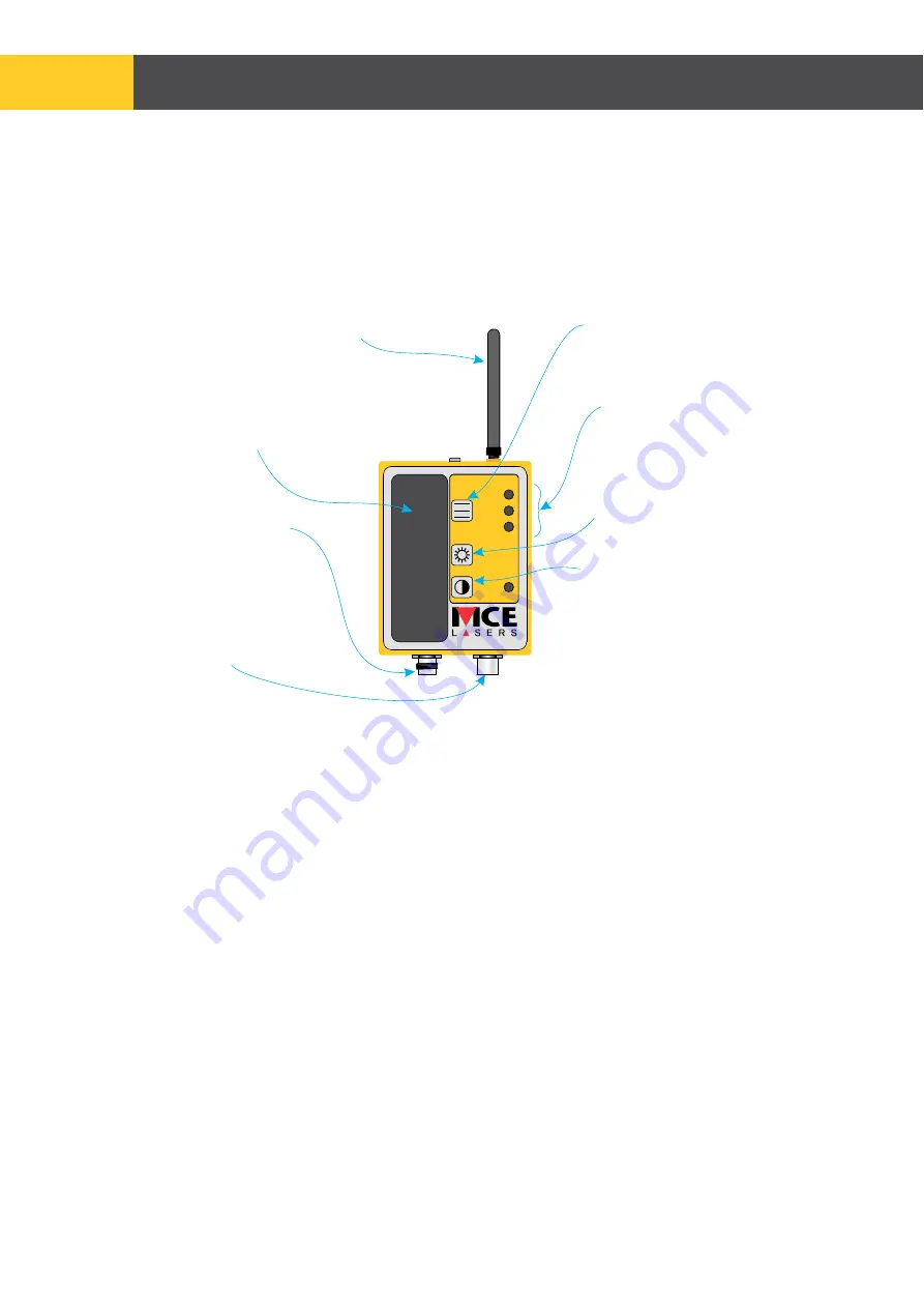
The receiver’s centreband can be changed via the Centre Band Select button on the 
DB.UNI.PRO. The current centreband selection is shown via the lit LED next to one of 

‘FINE’, ‘NORMAL’, or ‘WIDE’.
The DB.UNI.PRO’s LED brightness level can be changed via the Brightness Select button. 
One of five brightness levels can be selected.

5.1  DB.UNI.PRO

DB.UNI.PRO

Centre Band Select

(Accuracy)

Current Centre Band

Selection

BT Antenna

(not required if using CAN cable)

DB.UNI.PRO
Brightness Select

LED display mirroring

R.45.TC.PRO LED clusters

Power

Connector

CAN connector

(not used if using BT)

Switches off DB.UNI.PRO
when operating via BT.
Switches off both DB.UNI.PRO
and R.45.TC.PRO when
operating via CAN.

Figure 9

FINE

WIDE

MED

Bandwidth

Brightness

Power

ON

Summary of Contents for LASERGUIDE MINI

Page 1: ...USER MANUAL LASERGUIDE MINI R 45 TC PRO R 45 TC...

Page 2: ...h 2022 90 Willandra Drive Document number OM R45TC 12 This manual is an important part of your purchase Please read it thoroughly before using your new equipment Serial number We recommend that you re...

Page 3: ...necessary to repair machine mounted equipment under warranty MOBA Australia may authorize on site repairs at no charge for parts and labour Travel time accommodation and other expenses incurred to an...

Page 4: ...e is externally mounted on your machine Do not install or 4 Do not let any part of the unit protrude into traffic or limit the visibility of the 2 A construction site can be hazardous and working arou...

Page 5: ...Setting Up 8 2 5 Buzzer 12 4 CAN Connectivity Setup Optional R 45 TC PRO only 17 2 Using the Laserguide 8 3 BT Connectivity Setup Optional R 45 TC PRO only 14 1 Features of the Laserguide 6 2 2 1 Sett...

Page 6: ...ng Reference Mark 7 Bottom LED Cluster ORANGE 8 Accuracy Switch Centre Band 9 Reference Dial 10 On O Switch 11 Battery Compartment Holding Handle 12 Battery Cap 13 Magnetic Bracket Protective Plate 2...

Page 7: ...ORANGE 8 Accuracy Switch Centre Band 9 Reference Dial 10 On O Switch 11 CAN Connectors 12 Battery Cap 13 Dismounting Lever 14 Magnetic Bracket Protective Plate 2 5 6 11 13 12 1 3 4 7 9 8 10 Features...

Page 8: ...ion LED solid Tilt compensation feature is off The unit does not account for the dipper arm tilt when indicating correct digging depth This mode is less accurate Reference Dial 9 in Off position On po...

Page 9: ...or to section 2 2 2 if intending NOT to use the tilt compensation feature Setup Length Distance from bucket pivot pin to MT REF line mark on the side of the B Bucket height from bucket pivot pin to gr...

Page 10: ...equals the height of the laser instrument HI plus the desired depth of excavation C both with respect to the benchmark 6 Zero the setup position by pressing and holding together the Accuracy 8 and On...

Page 11: ...ings correct digging depth is achieved when the bucket orientation is in the level position 1 Ensure the dipper arm is vertical and the bucket is level L HI C 4 Mount the R 45 TC R 45 TC PRO sensor on...

Page 12: ...he R 45 TC R 45 TC PRO is receiving a laser beam the indication LEDs and buzzer will flash buzz at a slower frequency to alert the user 2 4 Accuracy Centre Band The R 45 TC R 45 TC PRO has three diffe...

Page 13: ...on LED will flash at a fast rate not to be confused with the slower flashing rate indicating compensation mode is switched on If a laser beam is on the receiving area at the time of low battery the f...

Page 14: ...TC PRO is in close proximity to the Android device 4 Go into the Android device s BT setup switch on the BT setting and select scan for 5 Open the MCE R45APP application At the bottom right hand side...

Page 15: ...with the DB UNI PRO The DB UNI PRO will automatically pair with the R 45 TC PRO and start to mirror its LED clusters If the two do not establish communication switch both off and on again See section...

Page 16: ...e the two are bought separately or if the two are not communicating the DB UNI PRO may need to be configured using the following steps 2 Switch on the R 45 TC PRO switch off the DB UNI PRO 3 3 Configu...

Page 17: ...he supplied CAN cable connect between the male connector of the DB UNI PRO A RS 105 5m Cigarette Lighter CAN Cables DB UNI PRO to R 45 TC PRO and the female connector of the R 45 TC PRO Once the units...

Page 18: ...le between the stick and bucket G2 sensors on the excavator 4 2 Connecting to the MOBA XSITE 2D Excavator see Figure 8 4 Follow the normal calibration procedure in the MOBA XSite manual cables Please...

Page 19: ...offset is measured from the centre line of the laser receiver to the centre line of the stick X offset can be calculated by measuring the thickness of the stick dividing the measure by two and adding...

Page 20: ...PRO s LED brightness level can be changed via the Brightness Select button One of five brightness levels can be selected 5 1 DB UNI PRO DB UNI PRO Centre Band Select Accuracy Current Centre Band Sele...

Page 21: ...imate distance to raise or lower the bucket Arrows indicate whether to raise or lower the bucket mirroring the R 45 TC PRO LED clusters 0mm R45PRO With tilt compensation switched on indicates R 45 TC...

Page 22: ...m Up to 42 1 D size Alkaline 45 hours Yes Yes 390 X 69 X 117mm 1 93kg No No R 45 TC PRO 190mm 600m 4mm Up to 42 4 C size Alkaline 70 hours Yes Yes No Yes External P S 12 24 VDC 296 X 90 X 116mm 2 13kg...

Page 23: ...h diese Erkl rung bezieht mit den folgenden Normen bereinstimmt to which this declaration relates is in conformity with the following standards auquel se r f re cette d claration est conforme aux norm...

Page 24: ...MOBA MOBILE AUTOMATION AUSTRALIA PTY LTD ABN 866 279 713 68 90 Willandra Drive Epping Victoria Australia 3076 Ph 61 3 9357 0055 www moba automation com au...

Reviews: