background image


MFP250 / 400 / 800 

Sequence 


76609594EN-MFP-NH-V2.0.docx 34/40 


5.3 

Diagrams 

5.3.1 

Welding Scheme Sequence 


5.3.2 

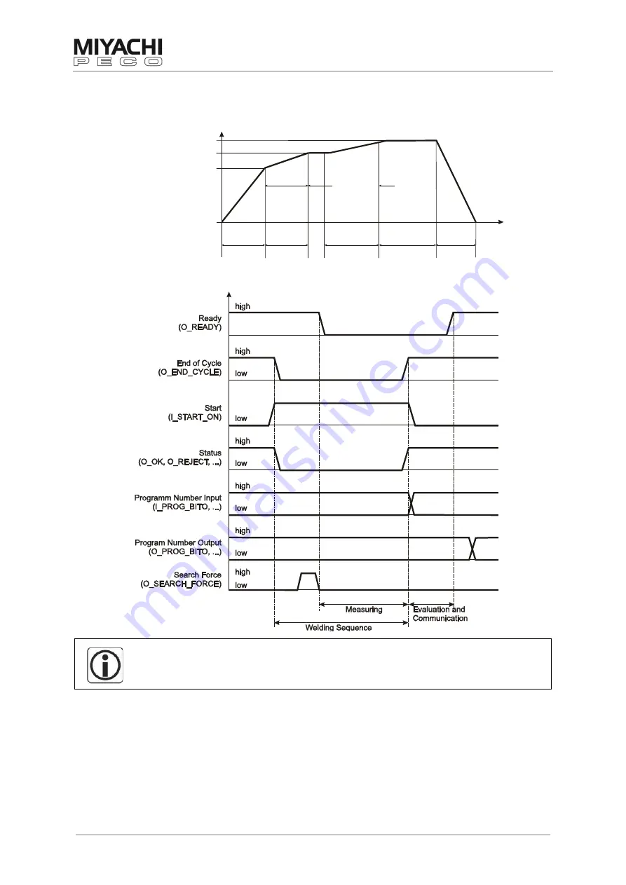
Signal Sequence Diagram MNC  


Start is accepted only if output 

Ready

 of the MNC as well as of the ISQ is activated. 

Otherwise a fault message is generated.  


This start signal must stay active until output 

Ready

 becomes inactive. Output 

Ready


gets active again when the next weld cycle can be started.  
Output 

End Of Cycle

 is activated when the full status information of the current 

measurement is available. 

End Of Cycle

 could stay inactive if a fault occurs. In that 

case the output 

Fault

 is activated. External program selection should be performed 

earliest after end of cycle. The duration of acknowledging that signal as well as the time 
for evaluation and communication could reach 

30 seconds

.  

Output 

Search Force

 is set when search force is reached and after squeeze time it will 

be reset again. This signal is available also in single step mode and during electrode 
reference mode. 

starting

search for

deposit

Start

searching
position

Startposition

search

travel

breaking-off 

point

Penetration

deposit
reached

hold-time

welding

follow-up

return

Position [Inc]

time  t [ms]

Summary of Contents for Amada MFP250 Series

Page 1: ...Original Instructions German Translation of Original Instructions 76609594EN MFP NH V2 0 Weld Head Series with Motor Control MNC MFP250 MFP400 MFP800 OPERATING INSTRUCTIONS ...

Page 2: ...afety Notes as annex 1 0b 2015 07 Changed company name 2 0 2017 09 New MFP250 two channel MNC control Copyright 2017 AMADA MIYACHI EUROPE GmbH Lindberghstr 1 82178 Puchheim Germany Right to make amendments reserved Deviations may occur All rights reserved The products named in this manual are only used for identification purposes and may be trademarks or registered trademarks of the respective com...

Page 3: ... 3 6 X31 I O MNC OUT two axis operation 13 3 3 7 X112A X112B X113A X113B Programmable Plugs 14 3 3 8 X112A X112B E A Digital one axis operation 14 3 3 9 X113A X113B E A Digital two axis operation 16 3 3 10 X112 X113 Default Assignment 17 3 3 11 X114 ENABLE 20 3 3 12 Plugs Motor Heads and Pincers 20 4 Initial Start Up 21 4 1 Electrical Connections 21 4 1 1 Mains Connection 21 4 1 2 Connecting Compo...

Page 4: ...NC 34 5 3 3 PLC Example for Programming MNC 35 5 4 Pneumatic Schemes 36 5 4 1 Locking Cylinder without Maintenance Unit 36 5 4 2 Locking Cylinder with Maintenance Unit optional 36 6 Accessory Electrodes 37 6 1 Copper Electrodes ø 6 mm 37 6 2 Insert Electrodes with Shaft ø 6 mm 37 6 3 Copper Electrodes ø 10 mm 38 6 4 Insert Electrodes with Shaft ø 10 mm 38 6 5 Electrodes 7 5 mm 38 7 Indexes 39 7 1 ...

Page 5: ...propriate configuration installation settings handling or use can cause mechanical electrical or thermal hazards which may result in serious damage or injury Ensure the correct execution of these points and follow the respective notes in the operating instructions Danger Do not put the system into operation before you have read the operating instructions Danger Persons with cardiac pacemakers and ...

Page 6: ...changer or spot arm customized Electrode Shape Ø 6 mm or 10 mm for pincers 7 5 mm Electrode stroke max 30 mm Supply Voltage 110 or 230 V AC depends on version Fuse Protection 10 A Protection Class IP30 2 2 Type Overview Weld Heads The weld heads are available in different types depending on model Machine type for automation with stand with or without stroke and pincers Machine type Pincers Stand S...

Page 7: ... cables a stand if it s a stand type electrode holders electrode quick changer a pair of electrodes The stand type with lower stroke cylinder contains the stroke cylinder which adjusts the backing electrode Servomotor driven weld pincers additionally consist of a basic pincer unit for vertical or horizontal installation The mounting of the weld head active side and of the passive side on the slide...

Page 8: ...d axis for double weld head systems For this you additionally need the motor head control MNCxxx A2 3 1 Technical Data Motor Head Control MNC Mains voltage 110 V or 230 V Mains frequency 50 60 HZ Connecting cable rubber connector Connected load MNC250 2 3 kVA Connected load MNC400 2 3 kVA Connected load MNC800 3 7 kVA Dimensions W x H x D 216 x 407 x 470 mm Protection class IP20 Cooling air cooled...

Page 9: ...motor is actuated The servomotor is located in the servo module of the motor head MFPxxx It powers a low friction spindle which is used for the transformation of the electrode motion During this the speed of high lift and return stroke of the electrodes and the distance covered are digitally specified monitored and displayed Torque can be utilized to accurately specify the welding pressure This is...

Page 10: ...Description Motor Head Control 76609594EN MFP NH V2 0 docx 10 40 3 2 1 Rear Panel Motor Head Control Axis 1 Fig 7 Rear panel MNC A1 Standard 1st axis The light painted connectors are options and not scope of delivery ...

Page 11: ...MFP250 400 800 Description Motor Head Control 76609594EN MFP NH V2 0 docx 11 40 Axis 2 Fig 8 Rear panel MNC A2 2nd axis ...

Page 12: ...RJ45 8 socket f X30 MOTOR socket f X31 I O MNC OUT 2 D SUB 15 socket f X31A Initiator 1 socket f X32 I O ISQ 2 D SUB 15 socket f X112A I O DIGITAL 1 D SUB 50 socket f X112B I O DIGITAL 1 D SUB 50 socket f X114 ENABLE 4 pin socket plug socket f 3 3 1 X6 I O ISQ one axis operation Plug Pin Function Note X6 1 Internal use X6 3 Internal use X6 4 Internal use X6 5 Internal use X6 8 Programmable output ...

Page 13: ...7 V24_RTS X17 8 V24_CTS X17 9 V24_RI 3 3 5 X18 Industrial Ethernet one axis operation optional Plug Pin Function X18 1 EN_TX X18 2 EN_TX X18 3 EN_RX X18 6 EN_RX 3 3 6 X31 I O MNC OUT two axis operation Plug Pin Function Note X31 1 Internal use X31 3 Internal use X31 4 Internal use X31 5 Internal use X31 8 Programmable output looped X31 9 ISQ_ 24V looped X31 10 ISQ_GND looped X31 11 Programmable ou...

Page 14: ... X112 10 I 23 Programmable input 4mA at 24V X112 11 I 24 Programmable input 4mA at 24V X112 12 I 25 Programmable input 4mA at 24V X112 13 I 26 Programmable input 4mA at 24V X112 14 I 27 Programmable input 4mA at 24V X112 15 I 28 Programmable input 4mA at 24V X112 16 I 29 Programmable input 4mA at 24V X112 17 I 30 Programmable input 4mA at 24V X112 18 I 31 Programmable input 4mA at 24V X112 19 I 32...

Page 15: ...RNAL EXT_GND with switch EXTERNAL Output int GND with switch INTERNAL Input ext GND with switch EXTERNAL X112 38 I 64 ISQ programmable input 100mA at 24V X112 39 O 64 ISQ programmable output 100mA at 24V X112 40 O 65 ISQ programmable output 100mA at 24V X112 41 O 66 ISQ programmable output 100mA at 24V X112 42 O 67 ISQ programmable output 2 5mA at 24V X112 43 O 68 ISQ programmable output 2 5mA at ...

Page 16: ... O 12 Programmable input or output 400mA 10mA at 24V X113 9 I O 11 Programmable input or output 400mA 10mA at 24V X113 10 O10 Ready axis 2 100mA at 24V X113 11 I O 68 ISQ_ 24V with INTERNAL switch EXT_ 24V with EXTERNAL switch Output int 24V Input ext 24V X113 12 I O 69 ISQ_GND with INTERNAL switch EXT_GND with EXTERNL switch Output int 24V Input ext 24V X113 13 O64 ISQ programmable output 100mA a...

Page 17: ...ke cylinder axis 2 ahead top P I27 X112 14 I_EOC_1 Stepping contact axis 1 P I_EOC_2 Stepping contact axis 2 P I_REL_CURR_1 Release current axis 1 P I_REL_CURR_2 Release current axis 2 P I_REF_ELEC_1 Start reference run axis 1 P I19 X112 6 X112 6 I_REF_ELEC_2 Start reference run axis 2 P I25 X112 12 I_CRTL_ON_1 Activating controller axis 1 D I_CRTL_ON_2 Activating controller axis 2 D I_CRTL_OFF_1 ...

Page 18: ...ler switched on axis 1 D A25 X112 28 X112 28 O_CRTL_ON _2 Controller switched on axis 2 D O_OK_1 Welding ok axis 1 P A26 X112 29 X112 29 O_OK_2 Welding ok axis 2 P A14 X113 6 O_REJECT_1 Welding not ok axis 1 P A27 X112 30 X112 30 O_REJECT _2 Welding not ok axis 2 P A13 X113 7 O_ERR_PART_1 Error part detection axis 1 P A28 X112 31 X112 31 O_ERR_PART_2 Error part detection axis 2 P A12 X113 8 O_ERR_...

Page 19: ...ogram Bit 7 P Not programmable MFP Outputs O_READY_1 axis 1 ready D A02 X112 50 X112 50 O_READY_2 axis 2 ready D A10 X113 10 ISQ Inputs I_RESET_CTR Reset counter P I_RESET_REJECT Reset welding not ok P I_RESET_FAULT Receipt fault D I_RESET_AC Reset action counter P ISQ Outputs O_READY ISQ ready D O_EOC End of Cycle P O_LIM_CTR Limit value counter P O_WARN_CTR Warning limit counter P O_REJECT_1 War...

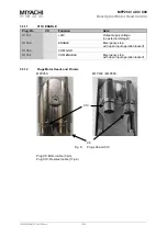
Page 20: ... 24V Output supply voltage no external voltage X114 2 ENABLE Emergency stop with open input operation locked X114 3 COM GND X114 4 COM ENABLE Emergency stop with open input operation locked 3 3 12 Plugs Motor Heads and Pincers MFP250 MFP400 MFP800 Fig 9 Plugs X9 and X10 Plug X9 Motor cable 7 pin Plug X10 Resolver cable 17 pin X10 X9 ...

Page 21: ...r this purpose Caution Connect the initiators etc Connect the power control of the AWS3 system with the motor control Connect the motor head Connect operation panel BT AWS3 Connect the units to mains 4 1 1 Mains Connection Observe mains voltage First compare the existing supply voltage to the voltage stated on the type label of the equipment Warning Valid regulations must be heeded for fusing and ...

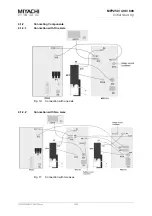
Page 22: ...800 Initial Start Up 76609594EN MFP NH V2 0 docx 22 40 4 1 2 Connecting Components 4 1 2 1 Connection with One Axis Fig 10 Connection with one axis 4 1 2 2 Connection with Two Axes Fig 11 Connection with two axes ...

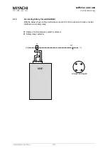
Page 23: ... 3 Connecting Safety Circuit ENABLE With the below shown wiring performance level d PL d is reached with a two channel shutdown via a safety relay S1 Safety circuit emergency switch customer K1 Safety relay customer Circ Conn K1 2 1 MNC S1 3 4 1 2 4 3 circular connector ...

Page 24: ... cables should be laid as closely as possible and bound with cable ties to maintain a limited secondary window Secondary cables should not be contacted to other parts conducting current and should not form shunt circuit Contact surfaces should be clean Contact surfaces should not be corroded Screw connections should not loosen during operation Caution When welding materials which are widely dispar...

Page 25: ...trol or the measuring device and is necessary if you want to work with voltage or power control Fig 14 Connection on weld head typical Fig 15 Connection on weld pincers typical Connect the voltage measuring cable to the corresponding connections 1 2 Connect the 5 pole plug of the voltage measuring cable to the corresponding socket on the welding current control or the measuring device if used ...

Page 26: ... 16 Pneumatic connection of locking cylinder typical Connect the compressed air connections of the locking cylinder with the respective connections 4 1 7 Connecting Stroke Cylinder Filtered oil free compressed air with a pressure of 6 bar is required for the stroke cylinder Deactivate the compressed air when connecting the plug in hoses Caution Fig 17 Pneumatic connection of stroke cylinder typica...

Page 27: ...ed depending on the control used Risk of injury For installation work deactivate the system Warning Crushing hazard During switching on off cylinders can move Maintain a safety distance to the weld head Fig 18 Proximity switch typical below the cover cap of the weld head Fig 19 Proximity switch typical below the cover cap in the stroke cylinder ...

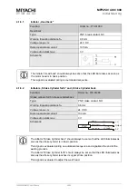
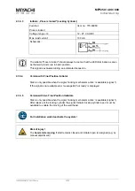
Page 28: ... back Function Stroke cylinder forth stroke cylinder back Order no 770 61293 Type PNP make contact NO Working triggering distance Sn 0 8 mm Voltage range Vs 24 V DC Rated operational current 100 mA Voltage drop static max 3 V Schematic The initiator Stroke Cylinder back should always be set so that the LED illuminates as soon as the stroke cylinder is in basic position This signal is evaluated dur...

Page 29: ...with Final Position Initiator Start is only possible when the signal locking mechanism active is available signal 1 If the signal is not available error message B2 not ready is displayed 4 1 8 5 Version with two Final Position Initiators Start is only possible when the signal locking mechanism active is available signal 1 After release of the locking cylinder the signal Initiator locking cylinder ...

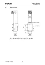
Page 30: ...MFP250 400 800 Initial Start Up 76609594EN MFP NH V2 0 docx 30 40 4 2 Mounting Scheme Fig 20 Mounting scheme MFPxxx machine type for automation ...

Page 31: ...Replace the quick changer incl the electrodes with a new and already adjusted pair of electrodes including the quick changer The advantage of this is that the reference run of the motor head needs not always to be readjusted 4 4 2 Setting the Welding Force The correct welding force for the welding task must be determined through several trial welding operations A generally applicable rule is that ...

Page 32: ... reference run of the motor head is performed after an initialization phase This means the motor head moves slow until it reaches the switching area of the built in initiator This adjustable initiator must be in the motor head s travel range Then the motor head leaves the switching area of the initiator designates this point as the reference point and then moves to basic position It moves to basic...

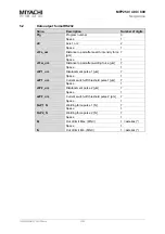
Page 33: ...e µm 7 Space 1 s1Fw_um Distance to part after welding force µm 7 Space 1 s3P1_um Displacement pulse 1 µm 7 Space 1 s2P1_um Current switch off threshold pulse 1 µm 7 Space 1 s3P2_um Displacement pulse 2 µm 7 Space 1 s2P2_um Current switch off threshold pulse 2 µm 7 Space 1 FwP1_N Welding force pulse 1 N 7 Space 1 FwP2_N Welding force pulse 2 N 7 Space 1 E Out of limit Max MNC 1 asterisk Space 1 E O...

Page 34: ...easurement is available End Of Cycle could stay inactive if a fault occurs In that case the output Fault is activated External program selection should be performed earliest after end of cycle The duration of acknowledging that signal as well as the time for evaluation and communication could reach 30 seconds Output Search Force is set when search force is reached and after squeeze time it will be...

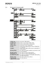
Page 35: ...well as of ISQ AWS3 in or conjunction O_READY Output ready of MNC AWS3 as well as of ISQ AWS3 in and conjunction M_EVALUATION PLC memory to activate evaluation of measurement reset at end of evaluation M_PART_IN_POS PLC memory for part in welding position M_RELEASE_PLC PLC memory to release start welding by PLC M_TRANSPORT_PART PLC memory to activate part transportation after welding reset after t...

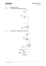
Page 36: ...MFP250 400 800 Sequence 76609594EN MFP NH V2 0 docx 36 40 5 4 Pneumatic Schemes 5 4 1 Locking Cylinder without Maintenance Unit 5 4 2 Locking Cylinder with Maintenance Unit optional ...

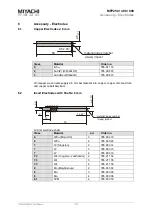
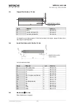
Page 37: ...nd copper cobalt beryllium 6 2 Insert Electrodes with Shaft ø 6 mm CuCrZr electrode shaft Class Material ø d Order no 6 WCu Elmet H3 3 765 83 470 6 WCu 4 765 83 324 7 W Tungsten 2 765 83 314 7 W 3 765 83 315 7 W 4 765 83 319 7 3 WL Tungsten Lanthanum 2 765 21 154 7 3 WL 3 765 21 155 7 3 WL 4 765 21 156 8 Mo Molybdenum 2 765 83 304 8 Mo 3 765 83 305 8 Mo 4 765 83 306 8 1 TZM 4 765 83 318 h11 6 ø 0 ...

Page 38: ... copper cobalt beryllium 6 4 Insert Electrodes with Shaft ø 10 mm CuCrZr electrode shaft Class Material ø d Order no 6 WCu Elmet H3 6 765 83 333 7 W Tungsten 3 765 83 338 7 W 4 765 83 339 7 W 6 765 83 336 7 3 WL Tungsten Lanthanum 3 765 21 157 7 3 WL 4 765 21 158 7 3 WL 6 765 21 159 8 Mo Molybdenum 3 765 83 311 8 Mo 4 765 83 312 8 Mo 6 765 83 313 8 1 TZM 6 765 15 898 8 1 TZM 8 765 17 711 6 5 Elect...

Page 39: ... with one axis 22 Fig 10 Connection with two axes 22 Fig 11 Secondary cable connection on weld head typical 24 Fig 12 Secondary cable connection on weld pincers typical 24 Fig 13 Connection on weld head typical 25 Fig 14 Connection on weld pincers typical 25 Fig 15 Pneumatic connection of locking cylinder typical 26 Fig 16 Pneumatic connection of stroke cylinder typical 26 Fig 17 Proximity switch ...

Page 40: ...ins Connection 21 Motor Head Control 8 Motor Head Control Design Mode of Action 9 Mounting Scheme 30 P PLC Example for Programming 35 Plugs Motor Heads and Pincers 20 Pneumatic Schemes 36 R Rear Panel Motor Head Control 10 Reference Run 32 RS232 Data output format 33 S Safety circuit 23 Sequence of a Welding Cycle 32 Setting the Electrodes 31 Setting the Welding Force 31 Setup 31 Signal Sequence D...

Reviews: