MFP250 / 400 / 800
Description Motor Head Control
76609594EN-MFP-NH-V2.0.docx 18/40
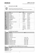
Symbol
Function
R
I/O
1 axis
operation
2 axis
operation
MFP Outputs
O_HOME_POS_1
Home pos. achieved axis 1
P
A21
X112.24
X112.24
O_HOME_POS_2
Home pos. achieved axis 2
P
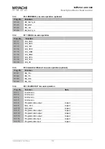
O_WAIT_POS_1
Waiting pos. achieved axis 1
P
A22
X112.25
X112.25
O_WAIT_POS_2
Waiting pos. achieved axis 2
P
O_SEARCH_FORCE_1
Search force built up axis 1
P
A23
X112.26
X112.26
O_SEARCH_FORCE _2
Search force built up axis 2
P
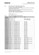
O_END_CYCLE_1
End of cycle axis 1
P
A24
X112.27
X112.27
O_END_CYCLE _2
End of cycle axis 2
P
O_INT_CYC_LOCK_1
Locking/stroke cylinder
axis 1 back/bottom
P
A31
X112.34
X112.34
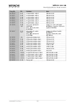
O_INT_CYC_LOCK_2
Locking/stroke cylinder
axis 2 back/bottom
P
A15
X113.5
O_INT_CYC_UNLK_1
Locking/stroke cylinder
axis 1 ahead/top
P
O_INT_CYC_UNLK_2
Locking/stroke cylinder
axis 2 ahead/top
P
O_CRTL_ON_1
Controller switched-on axis 1
D
A25
X112.28
X112.28
O_CRTL_ON _2
Controller switched-on axis 2
D
O_OK_1
Welding ok axis 1
P
A26
X112.29
X112.29
O_OK_2
Welding ok axis 2
P
A14
X113.6
O_REJECT_1
Welding not ok axis 1
P
A27
X112.30
X112.30
O_REJECT _2
Welding not ok axis 2
P
A13
X113.7
O_ERR_PART_1
Error part detection axis 1
P
A28
X112.31
X112.31
O_ERR_PART_2
Error part detection axis 2
P
A12
X113.8
O_ERR_DISPLM_1
Error displacement axis 1
P
A29
X112.32
X112.32
O_ERR_DISPLM _2
Error displacement axis 2
P
A11
X113.9
O_WARN_CTR_1
Warning limit counter axis 1
P
O_WARN_CTR_2
Warning limit counter axis 2
P
O_LIM_CTR_1
Limit counter axis 1
P
A30
X112.33
X112.33
O_LIM_CTR _2
Limit counter axis 1
P
O_DISPLM_MAX_1
Fault displacement max.
value axis 1
P
O_DISPLM_MAX_2
Fault displacement max.
value axis 2
P
O_DISPLM_MIN_1
Fault displacement min. value
axis 1
P
O_DISPLM_MIN_2
Fault displacement min. value
axis 1
P
O_FAULT_1
Fault axis 1
D
A08
X112.44
X112.44
O_FAULT _2
Fault axis 2
D
A16
X113.4
O_PROGV_1
Programmable valve axis 1
P
O_PROGV_2
Programmable valve axis 2
P

