background image

6.1 Comparison Operation Instructions

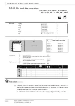
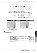
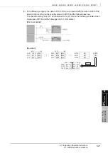
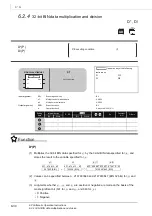
6.1.5 Character string data comparison

6-17

6

BA

S

IC


INSTRUCTIONS

…

$=,


…

$<>, 

…

$<=, 

…

$<,


…

$>=, 

…

$>

…

$=, 

…

$<>, 

…

$<=, 

…

$<, 

…

$>=, 

…

$>

Program

 E

xam

pl

e

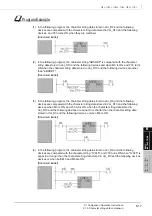
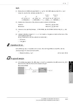
(1) In the following program, the character string data stored in Var_D0 and the following 

devices are compared with the character string data stored in Var_D10 and the following 
devices, and Y33 turns ON when they are matched.
[Structured ladder]

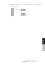
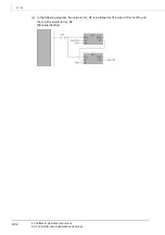
(2) In the following program, the character string "ABCDEF" is compared with the character 

string data stored in Var_D10 and the following devices and when M3 is ON, and Y33 turns 
ON when the character string data stored in Var_D10 and the following devices are other 
than "ABCDEF".
[Structured ladder]

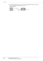
(3) In the following program, the character string data stored in Var_D0 and the following 

devices are compared with the character string data stored in Var_D10 and the following 
devices when M3 is ON, and Y33 turns ON when the character string data stored in 
Var_D10 and the following devices are equal to or shorter than the character string data 
stored in Var_D0 and the following devices, or when M8 is ON.
[Structured ladder]

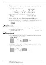
(4) In the following program, the character string data stored in Var_D0 and the following 

devices are compared with the character string "12345", and Y33 turns ON when "12345" is 
equal to or longer than the character string data stored in Var_D0 and the following devices 
devices or when both M3 and M8 are ON.
[Structured ladder]

Summary of Contents for MELSEC Q Series

Page 1: ...Structured Programming Manual Mitsubishi Programmable Controller QCPU Common Instructions ...

Page 2: ......

Page 3: ...rogrammable controller thoroughly read the manuals attached to the products and the relevant manuals introduced in the attached manuals Also pay careful attention to safety and handle the products properly Please keep this manual in a place where it is accessible when required and always forward it to the end user ...

Page 4: ...anual number Revision Jul 2008 SH NA 080783ENG A First edition This manual confers no industrial property rights or any rights of any other kind nor does it confer any patent licenses Mitsubishi Electric Corporation cannot be held responsible for any problems involving industrial property rights which may occur as a result of using the contents noted in this manual ...

Page 5: ...ns 2 6 2 3 3 Output instructions 2 6 2 3 4 Shift instructions 2 7 2 3 5 Master control instructions 2 7 2 3 6 End instructions 2 7 2 3 7 Other instructions 2 7 2 4 Basic instructions 2 8 2 4 1 Comparison operation instructions 2 8 2 4 2 Arithmetic operation instructions 2 13 2 4 3 Data conversion instructions 2 15 2 4 4 Data transfer instructions 2 17 2 4 5 Program branch instructions 2 18 2 4 6 P...

Page 6: ...els 3 4 3 2 2 Local labels 3 4 3 2 3 Label classes 3 4 3 2 4 Setting labels 3 5 3 2 5 Expressing methods of constants 3 5 3 3 Data Types 3 6 3 4 Method for Specifying Data 3 8 3 4 1 Bit data 3 8 3 4 2 Word 16 bits data 3 9 3 4 3 Double word 32 bits data 3 11 3 4 4 Single precision real double precision real data 3 13 3 4 5 String data 3 16 3 4 6 Arrays 3 17 3 4 7 Structures 3 19 3 5 Device and Add...

Page 7: ...Instructions 5 44 5 4 1 Bit device shift 5 44 5 5 Master Control Instructions 5 47 5 5 1 Setting and resetting master control 5 47 5 6 End Instructions 5 51 5 6 1 Ending main routine program 5 51 5 7 Other Instructions 5 53 5 7 1 Sequence program stop 5 53 6 BASIC INSTRUCTIONS 6 1 to 6 178 6 1 Comparison Operation Instructions 6 2 6 1 1 16 bit BIN data comparison 6 2 6 1 2 32 bit BIN data comparis...

Page 8: ...ing point data single precision 6 93 6 3 13 Sign inversion of floating point data double precision 6 95 6 3 14 16 bit BIN block data to 4 digit BCD block data conversion 6 97 6 3 15 4 digit BCD block data to 16 bit BIN block data conversion 6 100 6 3 16 Single precision to double precision conversion 6 103 6 3 17 Double precision to single precision conversion 6 105 6 4 Data Transfer Instructions ...

Page 9: ...t right left shift of n bit data 7 44 7 3 3 1 word right left shift of n word data 7 47 7 4 Bit Processing Instructions 7 50 7 4 1 Bit set and reset of word devices 7 50 7 4 2 Bit test 7 53 7 4 3 Batch reset of bit devices 7 56 7 5 Data Processing Instructions 7 58 7 5 1 16 32 bit data search 7 58 7 5 2 16 32 bit data bit check 7 62 7 5 3 Decoding from 8 to 256 bits 7 65 7 5 4 Encoding from 256 to...

Page 10: ... 7 11 11Floating point data to character string data conversion 7 194 7 11 12Character string data to floating point data conversion 7 201 7 11 13Hexadecimal BIN data to ASCII data conversion 7 206 7 11 14ASCII data to hexadecimal BIN data conversion 7 209 7 11 15Extraction of character string data from right left 7 212 7 11 16Random selection and replacement in character string data 7 215 7 11 17...

Page 11: ...Upper and lower limit controls of 16 32 bit BIN data 7 300 7 13 2 Dead band control of 16 32 bit BIN data 7 304 7 13 3 Zone control of 16 32 bit BIN data 7 308 7 14 Switch Instructions 7 312 7 14 1 Switching file register block numbers 7 312 7 14 2 Setting file register files 7 315 7 14 3 Setting files for comments 7 318 7 15 Clock Instructions 7 321 7 15 1 Reading clock data 7 321 7 15 2 Writing ...

Page 12: ...st CPU Shared Memory 8 52 8 11 1 Writing data to host CPU shared memory 8 53 8 11 2 Writing data to host CPU shared memory 8 57 8 12 Reading Data from Other CPU Shared Memory 8 60 8 12 1 Reading data from other CPU shared memory 8 61 8 13 Selection of Refresh Instructions 8 65 9 MULTIPLE CPU HIGH SPEED TRANSMISSION DEDICATED INSTRUCTIONS 9 1 to 9 20 9 1 Overview 9 2 9 2 Writing Device Data to Othe...

Page 13: ...structured programs Sold separately SH 080784ENG 13JW08 QCPU Structured Programming Manual Special Instructions Explains the specifications and functions of instructions for network modules intelligent function modules and PID control function that can be used in structured programs Sold separately SH 080785ENG 13JW09 Manual name Manual number Model code GX Works2 Version1 Operating Manual Common ...

Page 14: ...A 12 MEMO ...

Page 15: ... 3 CONFIGURATION OF INSTRUCTIONS 4 HOW TO READ INSTRUCTIONS 5 SEQUENCE INSTRUCTIONS 6 BASIC INSTRUCTIONS 7 APPLICATION INSTRUCTIONS 1 1 1 OVERVIEW 1 1 Purpose of This Manual 1 2 1 2 Generic Terms and Abbreviations in This Manual 1 4 ...

Page 16: ... Structured Project Common Simple Project Structured Project Installation Learning the operating environment and installation method Operation of Simple project Learning the basic operations and operating procedures Learning the functions and operation methods for programming Learning all functions and operation methods except for programming Operation of Structured project Learning the basic oper...

Page 17: ...ing the types and details of instructions for network modules Learning the types and details of instructions for the PID control function Programming in Structured project Learning the fundamentals for creating a structured program for the first time Learning the types and details of common instructions Learning the types and details of instructions for intelligent function modules Learning the ty...

Page 18: ...he Q02 QnHCPU Generic term for the Q02H Q06H Q12H and Q25H QnUCPU Generic term for the Q02U Q03UD Q03UDE Q04UDH Q04UDEH Q06UDH Q06UDEH Q13UDH Q13UDEH Q26UDH and Q26UDEH QnU D H CPU Generic term for the Q02U Q03UD Q04UDH Q06UDH Q13UDH and Q26UDH QnUD H CPU Generic term for the Q03UD Q04UDH Q06UDH Q13UDH and Q26UDH QnUDE H CPU Generic term for the Q03UDE Q04UDEH Q06UDEH Q13UDEH and Q26UDEH CPU modul...

Page 19: ...READ INSTRUCTIONS 5 SEQUENCE INSTRUCTIONS 6 BASIC INSTRUCTIONS 7 APPLICATION INSTRUCTIONS 2 2 1 INSTRUCTION TABLES 2 1 Types of Instructions 2 2 2 2 How to Read Instruction Tables 2 3 2 3 Sequence Instructions 2 5 2 4 Basic instructions 2 8 2 5 Application Instructions 2 20 ...

Page 20: ... Data processes such as 16 bit data search decode and encode Structured instruction Repeated operation subroutine program call index setting in units of ladder Data table operation instruction Data read write from to data tables Buffer memory access instruction Data read write from to intelligent function module Display instruction ASCII code print LED display of characters Debug error diagnostics...

Page 21: ...ion executes a instruction only when the operation result is TRUE Source Stores data before operation Destination Indicates the destination of data after operation 4 Indicates the processing details of each instruction Figure 2 2 Processing details of each instruction Category Function name Argument Processing details Execution condition Page Category Instruction name Argument Processing details E...

Page 22: ...struction is not executed and does not perform processing Indicates an executed once at ON type instruction that is executed only at the rising pulse OFF to ON of the precondition of the instruction The instruction is not executed afterwards even when the condition is ON and thus does not perform processing Indicates an executed while OFF type instruction that is executed only while the preconditi...

Page 23: ...tarts a logical operation with normally closed contact Performs a logical AND operation Normally open contact series connection Performs a negative AND operation Normally closed contact series connection Performs a logical OR operation Normally open contact parallel connection Performs a negative OR operation Normally closed contact parallel connection LDP Starts a rising pulse operation 5 4 LDF S...

Page 24: ...5 8 MRD Reads operation results stored in the MPS instruction MPP Reads and resets operation results stored in the MPS instruction INV Inverts operation results 5 11 MEP Operation result rising pulse 5 13 MEF Operation result falling pulse EGP Operation result rising pulse 5 15 EGF Operation result falling pulse Category Instruction name Argument Processing details Executing condition Page Output ...

Page 25: ...on Page Shift SFT 1 bit shift of a device 5 44 Category Instruction name Argument Processing details Executing condition Page Master control MC n Starts master control 5 47 MCR n Resets master control Category Instruction name Argument Processing details Executing condition Page Program end FEND Ends main program 5 51 Category Instruction name Argument Processing details Executing condition Page S...

Page 26: ... Non conduction state when 6 2 AND OR LD Conduction state when Non conduction state when AND OR LD Conduction state when Non conduction state when AND OR LD Conduction state when Non conduction state when AND OR LD Conduction state when Non conduction state when AND OR LD Conduction state when Non conduction state when AND OR s1 s2 s1 s2 s1 s2 s1 s2 s1 s2 s1 s2 s1 s2 s1 s2 s1 s2 s1 s2 s1 s2 s1 s2 ...

Page 27: ...E Conduction state when 1 1 Non conduction state when 1 1 6 8 ANDE ORE LDE Conduction state when 1 1 Non conduction state when 1 1 ANDE ORE LDE Conduction state when 1 1 Non conduction state when 1 1 ANDE ORE LDE Conduction state when 1 1 Non conduction state when 1 1 ANDE ORE LDE Conduction state when 1 1 Non conduction state when 1 1 ANDE ORE LDE Conduction state when 1 1 Non conduction state wh...

Page 28: ...te when 3 2 1 3 2 1 ANDED ORED LDED Conduction state when 3 2 1 3 2 1 Non conduction state when 3 2 1 3 2 1 ANDED ORED LDED Conduction state when 3 2 1 3 2 1 Non conduction state when 3 2 1 3 2 1 ANDED ORED LDED Conduction state when 3 2 1 3 2 1 Non conduction state when 3 2 1 3 2 1 ANDED ORED s1 s2 s1 s1 s1 s1 s2 s2 s2 s2 s1 s1 s1 s1 s2 s2 s2 s2 s1 s2 s1 s2 s1 s2 s1 s1 s1 s1 s2 s2 s2 s2 s1 s1 s1 ...

Page 29: ...acter by character 2 Conduction state when Character string of Character string of Non conduction state when Character string of Character string of AND OR LD Compares the character string of with the character string of character by character 2 Conduction state when Character string of Character string of Non conduction state when Character string of Character string of AND OR LD Compares the cha...

Page 30: ...age BIN block data comparison BKCMP n Compares the data n points from with the data n points from in 1 word units and stores the result to n points starting from the bit device specified for 6 18 BKCMP n BKCMP n BKCMP n BKCMP n BKCMP n BKCMP P n BKCMP P n BKCMP P n BKCMP P n BKCMP P n BKCMP P n s1 s2 d s1 s2 d s1 s2 d s1 s2 d s1 s2 d s1 s2 d s1 s2 d s1 s2 d s1 s2 d s1 s2 d s1 s2 d s1 s2 d s1 s2 d ...

Page 31: ...D 1 1 3 2 1 6 30 D 1 1 Quotient 1 Remainder 3 2 4 digit BCD data addition and subtraction B 6 33 B 8 digit BCD data addition and subtraction DB 1 1 1 6 35 DB 1 1 1 4 digit BCD data multiplication and division B 1 6 37 B Quotient Remainder 1 8 digit BCD data multiplication and division DB 1 1 3 2 1 6 39 DB 1 1 Quotient 1 Remainder 3 2 s1 s2 d s1 s2 d s1 s2 d s1 s2 d s1 s2 d s1 s1 s2 s2 d d s1 s2 d ...

Page 32: ... 1 Quotient 3 2 1 Block data addition and subtraction BK n Batch adds data of n points from and data of n points from 6 54 BK n Batch subtracts the data of n points from from the data of n points from Character string data concatenation Connects the character string specified for to the character string specified for and stores the result to and the following devices 6 57 BIN data increment and de...

Page 33: ...onversion DBL 6 83 WORD 6 85 s d BIN 0 to 9999 BCD conversion d s s d BIN 0 to 99999999 BCD conversion 1 1 d d s s s d BCD 0 to 9999 BIN conversion d s s d BCD 0 to 99999999 BIN conversion 1 1 d d s s s d BIN 32768 to 32767 Conversion to real number 1 d s s s d BIN 2147483648 to 2147483647 Conversion to real number 1 1 d d s s s d BIN 32768 to 32767 Conversion to real number 3 2 1 d d d d s s d BI...

Page 34: ...t to and the following devices 6 100 Floating point data single precision to double precision conversion ECON 6 103 Floating point data double precision to single precision conversion EDCON 6 105 s d BIN 32768 to 32767 Conversion to Gray code data d s s d BIN 2147483648 to 2147483647 Conversion to Gray code data 1 1 d d s s s d Gray code 32768 to 32767 Conversion to BIN data d s s d Gray code 2147...

Page 35: ... Transfers the character string data specified for to and the following devices 6 114 16 bit data negation transfer CML 6 117 32 bit data negation transfer DCML Block data transfer BMOV n 6 122 Same data block transfer FMOV n 6 126 16 bit data exchange XCH 6 129 32 bit data exchange DXCH Block data exchange BXCH n 6 132 Upper and lower bytes exchange SWAP 6 135 s d d s s d 1 1 d d s s s d Real num...

Page 36: ...P Unconditionally jumps to GOEND Jumps to the FEND instruction when the input condition is satisfied 6 140 Category Instruction name Argument Processing details Executing condition Page Disable interrupt DI Disables the execution of interrupt programs 6 142 Enable interrupt EI Cancels the execution disabled status of the interrupt program Disable enable interrupt setting IMASK Disables enables int...

Page 37: ... into n1 from the stop position to the position specified for 1 in the shortest path 6 163 Ramp signal RAMP n1 n2 n3 Changes the data of the device specified for from n1 to n2 in n3 scans 6 166 Pulse density SPD n Counts the pulse inputs of the device specified for for the time specified by n and stores the result to the device specified for 6 169 Pulse output PLSY n1 n2 6 171 Pulse width modulati...

Page 38: ...xecuting condition Page Logical AND WAND 7 3 DAND BKAND n 7 6 Logical OR WOR 7 9 DOR BKOR n 7 12 Exclusive OR WXOR 7 15 DXOR BKXOR n 7 18 Exclusive NOR WXNR 7 21 DXNR BKXNR n 7 24 s1 s2 d s1 s2 d s1 s2 d 1 s1 s1 1 s2 s2 1 d d s1 s2 d n s1 s2 d s1 s2 d s1 s2 d s1 s2 d 1 s1 s1 1 s2 s2 1 d d s1 s2 d n s1 s2 d s1 s2 d s1 s2 d s1 s2 d 1 s1 s1 1 s2 s2 1 d d s1 s2 d n s1 s2 d s1 s2 d s1 s2 d s1 s2 d 1 s1...

Page 39: ... DROL n 7 38 DRCL n d SM700 Rotates n bits to the right Carry flag b0 b15 d d SM700 Rotates n bits to the right b0 b15 Carry flag d d SM700 Rotates n bits to the left Carry flag b0 b15 d d SM700 Rotates n bits to the left Carry flag b0 b15 d d b0 b31 SM700 b16 to b15 to 1 Rotates n bits to the right Carry flag d d d b0 b31 SM700 b16 to b15 to Rotates n bits to the right Carry flag 1 d d d b0 b31 S...

Page 40: ...egory Instruction name Argument Processing details Executing condition Page n bit shift SFR n 7 41 SFL n 1 bit shift BSFR n 7 44 BSFL n 1 word shift DSFR n 7 47 DSFL n d b0 bn b15 0 to 0 b0 SM700 b15 Carry flag d b15 bn b0 0 to 0 b15 SM700 b0 Carry flag d n SM700 0 Carry flag d d n SM700 0 Carry flag d d n 0 d d n 0 d ...

Page 41: ... instructions Category Instruction name Argument Processing details Executing condition Page Bit set reset BSET n 7 50 BRST n Bit test TEST 7 53 DTEST Bit device batch reset BKRST n 7 56 d b0 bn b15 1 d d b0 bn b15 0 d s1 s2 d b0 b15 to Bit specified for s1 s2 d s1 s2 d b0 b31 to s1 d Bit specified for s2 s OFF OFF OFF OFF Reset n ON OFF ON ON s s ...

Page 42: ...the devices from and stores the result to and the following devices 7 76 NUNI Connects the data in and the following devices per bits specified by the devices from and stores the result to and the following devices WTOB n Separates 16 bit data specified for in units of 8 bits for n points of devices and stores the result in order from the device specified for 7 81 BTOW n Connects lower 8 bits of 1...

Page 43: ...s the minimum value to the device specified for 7 88 DMIN n Searches the data 2 multiplied by n points from the device specified for in units of 32 bits and stores the minimum value to the device specified for Sort SORT n Sorts the data n points from the device specified for in units of 16 bits n multiplied by n 1 2 scans required 7 91 DSORT n Sorts the data 2 multiplied by n points from the devic...

Page 44: ...uction loop and jumps to the pointer 7 103 Subroutine program call CALL Executes the subroutine program when the input condition is satisfied 7 106 RET Returns from the subroutine program 7 108 COM Performs link refreshes and general data processes 7 110 Category Instruction name Argument Processing details Executing condition Page Data table process FIFW 7 113 FIFR 7 116 FPOP 7 119 FDEL n 7 122 F...

Page 45: ...ame Argument Processing details Executing condition Page ASCII print PR When SM701 is OFF outputs 8 points of ASCII code 16 characters from the device specified for to the output module 7 132 PR When SM701 is ON outputs ASCII code data from the device specified for up to 00H to the output module PRC Converts comments in the device specified for to ASCII code data and outputs the result to the outp...

Page 46: ...ed for to 8 digits of decimal ASCII data and stores the result to and the following word devices Decimal ASCII data to BIN data conversion DABIN Converts 5 digits of decimal ASCII data specified for to 1 word of BIN data and stores the result to the word device specified for 7 166 DDABIN Converts 10 digits of decimal ASCII data specified for to 2 words of BIN data and stores the result to the word...

Page 47: ...d of BIN value and number of digits for decimal fraction and stores the result to the devices specified for and 7 189 DVAL Converts character string data contain a decimal point specified for to 2 words of BIN data and number of digits for decimal fraction and stores the result to the devices specified for and Floating point data to character string data conversion ESTR Converts floating point dat...

Page 48: ...e specified for 7 215 MIDW Stores the specified number of characters from the character string data to the position specified for of the character string data INSTR n Searches for the character string data from the nth character of the character string data and stores matched positions to 7 220 Floating point data to BCD format data conversion EMOD Converts floating point data to BCD data of the d...

Page 49: ...root SQR 7 262 SQRD 7 264 Exponential EXP 7 266 EXPD 7 269 Natural logarithm LOG 7 272 LOGD 7 275 s d Sin 1 1 d d s s s d Cos 1 1 d d s s s d Tan 1 1 d d s s s d 1 Sin 1 1 d d s s s d 1 Cos 1 1 d d s s s d 1 Tan 1 1 d d s s s d Sin 3 2 1 s s s s 3 2 1 d d d d s d Cos 3 2 1 s s s s 3 2 1 d d d d s d Tan 3 2 1 s s s s 3 2 1 d d d d s d Sin 3 2 1 s s s s 3 2 1 d d d d 1 s d Cos 3 2 1 s s s s 3 2 1 d ...

Page 50: ... 16 bit BIN data stored in the device specified for Square root BSQR 7 279 BDSQR Trigonometric functions BSIN 7 283 BCOS 7 286 BTAN 7 289 BASIN 7 292 BACOS 7 295 BATAN 7 298 d d d s s d 0 1 Integer part Decimal fraction d s s d 0 1 Integer part Decimal fraction 1 d s s s d Sin 1 Integer part Decimal fraction 2 Sign 0 d s s d 1 Sign Decimal fraction 2 Integer part Cos 0 d s s d 1 Sign Decimal fract...

Page 51: ...the values of 1 to 1 When 1 1 stores the values of 1 to 1 Dead band control BAND When 0 When When 7 304 DBAND When 1 1 1 0 1 When 1 1 1 1 1 When 1 1 1 1 1 Zone control ZONE When 0 0 When 0 When 0 7 308 DZONE When 1 0 0 1 When 1 0 1 1 1 When 1 0 1 1 1 s1 s2 s3 d s3 s1 s1 d s1 s3 s2 s3 d s2 s3 s2 d s1 s2 s3 d s3 s3 s1 s1 s1 s1 d d s1 s1 s3 s3 s2 s2 s3 s3 d d s2 s2 s3 s3 s2 s2 d d s1 s2 s3 d s1 s3 s2...

Page 52: ...as a comment file 7 318 Category Instruction name Argument Processing details Executing condition Page Clock data read write DATERD 7 321 DATEWR 7 324 Clock data addition subtraction DATE 7 327 DATE 7 330 Clock data conversion SECOND 7 333 HOUR 7 335 s s s s d Clock elements Year Month Day Hour Sec Day of the week 1 2 3 4 5 6 Minute 0 d s Year Month Day Hour Sec Day of the week 1 2 3 4 5 6 Clock e...

Page 53: ...in the standby status 7 337 POFF Turns OFF the coil of the OUT instruction of the specified program and sets the program in the standby status 7 339 PSCAN Registers the specified program as a scan execution type program 7 341 PLOW Registers the specified program as a low speed execution type program 7 343 LDPCHK Conduction state when the program of the specified file name is in execution Non condu...

Page 54: ...ic input from keyboard KEY n Imports ASCII data into 8 points of the input module specified for converts the data to hexadecimal data and stores the result to and the following devices 7 360 Batch save of index register ZPUSH Saves the contents of index registers Z0 to Z15 to and the following devices 7 365 Batch recovery of indexregister ZPOP Reads data saved in and the following devices into the...

Page 55: ...ed in the memory card or standard memory other than drive 0 to drive 0 and sets the program in the standby status 8 38 Program unload from program memory PUNLOADP Deletes a standby program stored in the program memory drive 0 from the memory 8 42 Load unload PSWAPP Deletes a standby program stored in the program memory drive 0 specified for from the memory and transfers a program stored in the mem...

Page 56: ...o refresh of the intelligent function module and the auto refresh of general data and CPU shared memory 8 65 Category Instruction name Argument Processing details Executing condition Page Device data write to other CPU D_DDWR n1 Writes data stored in the device and the following devices in the host CPU at the time of multiple CPU system configuration to the device and the following devices specifi...

Page 57: ...Configuration of Instructions 3 2 3 2 Labels 3 4 3 3 Data Types 3 6 3 4 Method for Specifying Data 3 8 3 5 Device and Address 3 20 3 6 EN and ENO 3 22 3 7 Index Setting 3 23 3 8 Precautions on Programming 3 34 3 9 Executing Conditions for Instructions 3 39 3 10 Operation of OUT Instructions SET RST Instructions or PLS PLF Instructions Using Same Device 3 40 3 11 Precautions on Using File Registers...

Page 58: ...ming so that they cannot be changed while the program is being executed Perform index setting when using them as variable data Bit device and word device Specifies the device in which the data used in the operation are stored Data must be stored to the specified device before executing the operation By changing the data to be stored to the specified device while a program is being executed the dat...

Page 59: ...sfer instruction b A value in the range of 0 to 32767 can be set for the number of devices and number of transfers When the number of devices or number of transfers is 0 the instruction performs no processing 4 Executing condition EN a An input variable EN inputs an executing condition of an instruction 5 Execution status ENO a An output variable ENO outputs an execution status Specifies the numbe...

Page 60: ... be selected according to the type of POU The following table shows label classes Table 3 2 3 1 Label classes Class Description Applicable POU Program block Function Function block VAR_GLOBAL Common label that can be used in program blocks and function blocks VAR_GLOBAL_CONSTANT Common constant that can be used in program blocks and function blocks VAR Label that can be used within the range of de...

Page 61: ...ble shows the expressing method for setting a constant to a label Table 3 2 5 1 Constant expressing method Constant type Expressing method Example Bool Input FALSE or TRUE or input 0 or 1 TRUE FALSE Binary Append 2 in front of a binary number 2 0010 2 01101010 Octal Append 8 in front of an octal number 8 0 8 337 Decimal Directly input a decimal number or append K in front of a decimal number 123 K...

Page 62: ...functions refer to the following manual QCPU Structured Programming Manual Application Functions Data type Description Value range Bit length Bit Bool 0 FALSE 1 TRUE 1 bit Word signed Integer 32768 to 32767 16 bits Double word signed Double precision integer 2147483648 to 2147483647 32 bits Word unsigned 16 bit string 16 bit string 0 to 65535 16 bits Double word unsigned 32 bit string 32 bit strin...

Page 63: ...on Appendix 1 Correspondence between Generic Data Types and Devices The higher ANY data types include sub level data types The highest ANY data type includes all data types ANY_REAL ANY_INT Single precision real ANY_NUM Word unsigned 16 bit string Word signed ANY16 Double word unsigned 32 bit string Double word signed ANY32 Word signed Double word signed Double precision real ANY_BIT ANY_SIMPLE AN...

Page 64: ...e that bit specifications are not applicable for timers T retentive timers ST counters C and index registers Z Example Z0 0 is not available Word Signed data Data that can be handled by CPU module Bit data Numeric data Character string data Integer data Real number data Single precision real data Double precision real data Double word Signed data Section 3 4 2 Section 3 4 1 Section 3 4 4 1 Section...

Page 65: ...t can be specified in the range from K1 to K4 in unit of 4 points 4 bits For a link direct device specify as J To specify X100 to X10F of Network No 2 specify as J2 K4X100 The followings are the examples of the target points when a digit is specified for X0 K1X0 4 points of X0 to X3 K2X0 8 points of X0 to X7 K3X0 12 points of X0 to XB K4X0 16 points of X0 to XF Figure 3 4 2 1 Digit specification s...

Page 66: ...a digit specification a desired value can be used for the start device number of bit devices 2 Digits cannot be specified for direct access inputs outputs DX DY Ladder example Processing Instruction that processes 16 bit data Ladder example Processing When the source is a numeric value When the source is a word device 0 0 X3 b0 D0 K1X0 b1 b2 b3 0 0 0 0 0 0 0 0 0 0 X2 X1 X0 0s are stored X3 X2 X1 X...

Page 67: ...ed for X0 Figure 3 4 3 1 Digit specification setting range of double word data 32 bits b The following table shows the numeric values that can be used as source data when a digit is specified at the source Table 3 4 3 1 List of digit specification and numeric values that can be used K1X0 4 points of X0 to X3 K5X0 20 points of X0 to X13 K2X0 8 points of X0 to X7 K6X0 24 points of X0 to X17 K3X0 12 ...

Page 68: ...it devices 2 Digits cannot be specified for direct access inputs outputs DX DY Ladder example Processing Instruction that processes 32 bit data Ladder example Processing When the source is a numeric value When the source is a word device 0 0 X3 b0 D0 K1X0 b1 b2 b3 0 0 0 0 0 0 0 0 0 0 X2 X1 X0 0s are stored X3 X2 X1 X0 0 0 D1 0 0 0 0 0 0 0 0 0 0 0 0 0 0 0s are stored b31 b16 b15 b4 X10 DMOV EN ENO ...

Page 69: ...nd specified device number 1 Remark Floating point data are represented by two word devices Sign 1 Fraction 2 Exponent The following explains the bit configuration and its meaning when floating point data are internally represented Sign b31 represents a sign 0 Positive 1 Negative Exponent b23 to b30 represent n of 2n The values of n are as follows according to BIN values of b23 to b30 Fraction 23 ...

Page 70: ...point data are internally represented Sign b63 represents a sign 0 Positive 1 Negative Exponent b52 to b62 represent n of 2n The values of n are as follows according to BIN values of b52 to b62 Fraction 52 bits of b0 to b51 represent a value of XXXXXX when the fraction is expressed as 1 XXXXXX in binary M0 EDMOV EN ENO d Var_D0 Var_R100 Four points 64 bits of R100 R101 R102 and R103 are the target...

Page 71: ... that performs an internal operation of floating point operation with single precision a floating point operation results an error since the process speed is given a priority and 0 is used for an operation as it is when 0 is specified a The following is the CPU module in which the operation does not result an error when 0 is specified High Performance model QCPU in which the internal operation is ...

Page 72: ...NULL code to D2 The NULL code is stored to the last one word 3 When the number of characters is an odd number Character string data and NULL code are stored by using the number of characters 2 words Rounding the decimal fraction For example when ABCDE is transferred to word devices starting from D0 the character string ABCDE and the NULL code are stored to D0 to D2 The NULL code is stored to the h...

Page 73: ... in by For the ST and structured ladder languages labels word signed or double word signed data type can be used for indexes as shown below Note that Z0 or Z1 cannot be used in the programs if labels are used for indexes Number of array dimensions Format One dimension Array of elementary data type structure name array start value array end value Definition example Bit 0 2 Two dimensions Array of e...

Page 74: ...um number of array elements differs depending on data types as shown below Table 3 4 6 2 Maximum number of array Data type Maximum number Bit word signed word unsigned 16 bit string timer counter and retentive timer 32768 Double word signed double word unsigned 32 bit string single precision real and time 16384 Double precision real 8192 String 32768 divided by string length ...

Page 75: ... name after the structured data type label name with as a delimiter in between Structures can also be used as arrays When a structure is declared as an array append an index enclosed by after the structured data type label name dut_a1 in00 Structured data type label name Element name Example When using the element of the structured data dut_b1 0 in00 Index Element name Structured data type label n...

Page 76: ...rmat that conforms to IEC61131 3 Table 3 5 2 1 Address definition specifications Position Position is a major class indicating the position to which data are allocated in three types input output and internal The following shows the format rules corresponding to the device format X J X X device I input Y J Y Y device Q output Other devices M internal Start 1st character position 2nd character data...

Page 77: ...d D double word L long word Classification Classification is a minor class indicating the type of a device that cannot be identified only by its position and size Devices X and Y do not support classification For the format corresponding to the device format refer to the following section Appendix 2 Correspondence between Devices and Addresses Long words are used in double precision real operation...

Page 78: ...FALSE Operation stop FALSE Undefined value No Control description When the EN input is directly connected from the left base line the EN input is always TRUE and the instruction is always executed If the ADD_E instruction is used in this manner the operation result is the same as the ADD instruction without the EN input When Variable_1 is connected to the EN input the instruction is executed when ...

Page 79: ...ctions and application instructions except for the restrictions shown in the tables below 1 Devices that cannot be used for the index setting 1 SFC transition devices and SFC block devices are devices for SFC programs For details refer to the following manual QCPU Q mode QnACPU Programming Manual SFC 2 Devices with restrictions on index registers Device Description K H 32 bit constants E Floating ...

Page 80: ...0Z4 X1 OUT_C EN ENO s1 s2 CC100 10 SM400 BCD EN ENO s d CN100Z6 K4Y30 K2Y40 Set value of timer Index setting is not applicable Current value of timer Set value of counter Index setting is not applicable Current value of counter X0 MOV EN ENO d s Z0 K20 MOV EN ENO d s Z1 K 5 X1 MOV EN ENO d s K1M38Z1 K2X50Z0 X1 MOV EN ENO d s K1M33 264 Description Converts K20 to a hexadecimal number K2X50Z0 K1M38Z...

Page 81: ...483647 can be set to index registers The following shows how the index is set 2 Specification method When setting indexes in 32 bit range specify the start number of index registers to be used in the device setting of the PLC parameter in GX Works2 Figure 3 7 2 Index setting for ZR device on the parameter setting screen When changing the start number of index registers to be used in the device set...

Page 82: ...tual processing devices b Specifying a 32 bit index setting using ZZ 1 A 32 bit index can be specified to the index register by specifying an index using ZZ for instance ZR0ZZ4 The following figure shows the 32 bit index setting using ZZ Device Description ZR Serial number access file register D Extended data register W Extended link register Setting value Index register Setting value Index regist...

Page 83: ...sage range of index registers when specifying 32 bit index setting using ZZ When specifying a 32 bit index setting using ZZ specify a device as a form of ZRmZZn The device number of ZRm is indexed with 32 bits Zn Zn 1 by specifying ZRmZZn 1 Indicates the device name ZR to be indexed Device Description ZR Serial number access file register D Extended data register W Extended link register ZZ 1 Inde...

Page 84: ...be used individually such as DMOV K100000 ZZ0 When setting a value to index registers to specify a 32 bit index setting using ZZ set a value to Zn Z0 to Z19 ZZn cannot be entered individually in the functions of GX Works2 Ladder example Actual processing device No Description 1 Device specification of instructions in a program 2 Watch function 3 Current value change function 4 Sampling trace Trace...

Page 85: ... user devices and extended data registers D extended link registers W cannot be applied If the device range check is enabled at the index setting an error occurs Error code 4101 User program D device image Internal user device Extended deta register Z0 0 D100 D1100 D20000 D22000 Z0 1000 Z1 0 Z1 2000 The index setting applied to the extended data register The index setting applied to the internal u...

Page 86: ... applicable to the specified digits User program MOV EN ENO d s D100Z0 1234 MOV EN ENO d s D20000Z1 1234 Z0 0 Z0 10000 ZR100 D14196 File register file File register 8K points Z1 0 Z1 4000 D20000 W2DC0 Extended data register D 8K points From D12288 Extended link register W 8K points From W2000 Z1 10000 Even when the index setting that crosses extended data register D and extended link register W is...

Page 87: ...ing manual QCPU User s Manual Function Explanation Program Fundamentals e A 32 bit index setting is applicable to extended data register D and extended link register W for Universal model QCPU When applying an index setting to extended data registers D or extended link registers W it can be applied in 32 bit range as applying an index setting to file registers ZR in the following two methods Speci...

Page 88: ... is output normally M0Z1 pulse is not output normally Remark The ON OFF information of X0Z1 is stored to the edge relay V0Z1 For example the ON OFF data of X0 is stored to V0 and the ON OFF data of X1 is stored to V1 Z0 and Z1 cannot be used when labels are used for array indexes within the FOR to NEXT instruction loop SM400 MOV EN ENO d s Z1 0 FOR EN ENO n 10 X0Z1 EGP EN ENO d V0Z1 OUT EN ENO d M...

Page 89: ...ange specified by a user and the data are written to devices for the system an error occurs Error code 1103 Create a program with caution when applying the index setting 2 For Universal model QCPU The device range is checked when the index setting is applied By changing the settings of the PLC parameter on GX Works2 the device range is not checked d Switching between 16 bit and 32 bit range of the...

Page 90: ...follows 1 For High Performance model QCPU An error does not occur even when writing reading data to from file registers However 0H is stored when reading from file registers 2 For Universal model QCPU The OPERATION ERROR error code 4101 occurs when writing reading data to from file registers 1 Device range check The following explains how the range is checked for devices used in basic instructions...

Page 91: ...ration error occurs For example when data registers are assigned in 12k points an error occurs if the data exceed D12287 Device range is checked even when the index setting is applied However when the start number of the device exceeds the corresponding device range with the index setting an error occurs DMOV EN ENO d s D12287 100 This specifies D12287 and D12288 as the target devices for executin...

Page 92: ...data without exception the device range is checked When the data exceed the corresponding device range an operation error occurs For example when data registers are assigned in 12k points an error occurs if the data exceed D12287 BMOV EN ENO d s n D12287 D0 2 This specifies D12287 and D12288 as the target devices for executing the BMOV instruction However since D12288 does not exist an operation e...

Page 93: ... in the PLC parameter errors will not be detected even when the data accesses described in 1 to 4 above are performed However the operation differs according to the serial number of the Universal model QCPU as show in the following table 2 For changing the setting of device range check refer to the following manual QCPU User s Manual Function Explanation Program Fundamentals For Universal model QC...

Page 94: ...1 Checks whether each digit has a BCD value 0 to 9 If each digit has a value other than 0 to 9 A to F an operation error occurs 2 Even if the operation results in overflow or underflow an error does not occur and the carry flag is not turned ON c Floating point data If the operation results are as follows in an instruction that performs floating point operation an operation error occurs 1 0 2 127 ...

Page 95: ...ulse OFF to ON of the input condition Example PLS instruction MOVP instruction Executed at falling pulse Instructions executed only at the falling pulse ON to OFF of the input condition Example PLF instruction For basic instructions and application instructions that are equivalent to coils when both Executed while ON and Executed at rising pulse are applicable P is appended to an instruction name ...

Page 96: ... OFF according to the operation result obtained by each execution of the OUT instruction Since the ON OFF status of the specified device is determined by each execution of the OUT instruction turning ON OFF may be repeated during one scan The following figures show the operation example of the ladder that turns ON OFF the same internal relay M0 by the inputs X0 and X1 Ladder Timing chart For refre...

Page 97: ...he specified device is turned OFF when any of the execution commands is turned ON c If the SET and RST instructions use the same device in one scan the SET instruction turns ON the specified device when the execution command is ON while the RST instruction turns OFF the specified device when the execution command is ON When the execution command of the SET and RST instructions is OFF the ON OFF st...

Page 98: ...turns from OFF to ON In the status other than turning from OFF to ON they turn OFF the specified device Thus when the PLS instructions that use a same device are executed multiple times during one scan the devices turned ON in the PLS instructions may not be turned ON for one scan Ladder Timing chart The ON OFF timing differs between X0 and X1 The specified device is not turned ON for one scan PLS...

Page 99: ...d device If the PLF instructions that use a same device are executed multiple times during one scan the PLF instructions turn ON the specified device when the execution command turns from ON to OFF In the status other than turning from ON to OFF they turn OFF the specified device Thus when the PLF instructions that use a same device are executed multiple times during one scan the devices turned ON...

Page 100: ...ND X0 X1 M0 OFF OFF ON ON PLF EN ENO d M0 X1 PLF EN ENO d M0 X0 PLF EN ENO d M0 X1 PLF EN ENO d M0 X0 M0 turns ON because X0 goes OFF ON OFF M0 turns OFF because X1 status is other than ON OFF M0 turns OFF because X1 status is other than ON OFF M0 remains OFF M0 turns OFF because X0 status is other than ON OFF M0 remains OFF OFF ON END END END X0 X1 M0 OFF OFF ON ON PLF EN ENO d M0 X1 PLF EN ENO d...

Page 101: ...e CPU module Note that the data cannot be written read correctly to from file registers For the Universal model QCPU an error occurs if the program that uses file registers is executed 2 Reserving the file register area a For High Performance model QCPU and Universal model QCPU To use file registers register them to the standard RAM memory card and reserve the file register area The following tabl...

Page 102: ... Block switching method The block switching method specifies file register points being used in units of 32k points one block File registers exceeding 32k points is specified by switching block numbers of the file registers used in the RSET instruction File register points are specified in the range from R0 to R32767 for each block b Serial number access method The serial number access method spec...

Page 103: ... refresh data use the QDRSET instruction to switch to the corresponding file register 2 The refresh cannot be performed correctly if the file name of file register or drive number is changed by using the QDRSET instruction When the file name or drive number is changed by using the QDRSET instruction the link refresh is performed to the set file at the END instruction execution To read or write the...

Page 104: ...emory can be used for the QCPU QCPU Flash card b File registers in a flash memory can be only read in sequence programs File registers cannot be written to a flash memory in sequence programs When using a flash memory for file registers write data to a flash memory in advance c For QCPU Use GX Works2 to write data to a flash card BMOV EN ENO n d s D100 R0 10 BMOV s d EN ENO n D0 10 R100 Read Flash...

Page 105: ...1 OVERVIEW 2 INSTRUCTION TABLES 3 CONFIGURATION OF INSTRUCTIONS 4 HOW TO READ INSTRUCTIONS 5 SEQUENCE INSTRUCTIONS 6 BASIC INSTRUCTIONS 7 APPLICATION INSTRUCTIONS 4 4 1 HOW TO READ INSTRUCTIONS ...

Page 106: ...4 2 Chapter 5 to 9 provide detailed explanation on each instruction in the layout as shown below Indicates a section number and an outline of an instruction Indicates an instruction to be explained 1 2 ...

Page 107: ...ON Executed once at ON Executed while OFF Executed once at OFF Symbols on the corresponding page No symbol Elementary data type Type Description Direct device setting Bit Bool Uses bit data or bit device Data range 0 FALSE 1 TRUE Word signed Integer Uses signed word data Data range 32768 to 32767 Double word signed Double precision integer Uses signed double word data Data range 2147483648 to 2147...

Page 108: ...rmed by the instruction Indicates whether to exist the related error When an error exists conditions that cause an error are described Indicates program examples in the structured ladder and ST languages Generic data type Description ANY Can use all elementary data types ANY_NUM Can use elementary data type of single precision real double precision real word signed and double word signed ANY_REAL ...

Page 109: ...UENCE INSTRUCTIONS 6 BASIC INSTRUCTIONS 7 APPLICATION INSTRUCTIONS 5 5 1 SEQUENCE INSTRUCTIONS 5 1 Contact Instructions 5 2 5 2 Bond Instructions 5 6 5 3 Output Instructions 5 18 5 4 Shift Instructions 5 44 5 5 Master Control Instructions 5 47 5 6 End Instructions 5 51 5 7 Other Instructions 5 53 ...

Page 110: ...operation start instruction They read ON OFF information from the specified device 1 and use that as the operation result 1 When a bit specification is made for a word device the device turns ON or OFF depending on the 1 0 status of the specified bit Devices used as contacts Bit Setting data Internal device R ZR J U G Zn Constant Others DX BL Bit Word Bit Word Universal UD High Performance X1 D0 1...

Page 111: ...ction instruction and ORI is the normally closed single parallel connection instruction They read ON OFF information from the specified device 3 and perform an OR operation with the operation results to that point and use the resulting value as the operation result 3 When a bit specification is made for a word device the device turns ON or OFF depending on the 1 0 status of the specified bit Remar...

Page 112: ...n the specified bit changes from 0 to 1 In cases where there is only an LDP instruction it acts identically to instructions for the creation of a pulse that are executed while ON P LD P F AND P F OR P F indicates any of the following instructions LDP LDF ANDP ANDF ORP ORF Input argument EN Executing condition Bit s Devices used as contacts Bit Output argument ENO Execution result Bit Setting data ...

Page 113: ...ORP is a rising pulse parallel connection instruction and ORF is a falling pulse serial connection instruction They perform OR operations with the operation result to that point and take the resulting value as the operation result The ON OFF data used by ORP and ORF are indicated in the table below Operation Error No operation error occurs in the execution of the LDP LDF ANDP ANDF ORP and ORF inst...

Page 114: ...an OR operation on Block A and Block B and takes the resulting value as the operation result 2 ORB is used to perform parallel connections for ladder blocks with two or more contacts For ladder blocks with only one contact use OR or ORI there is no need for ORB in such cases Structured ladder 3 The ORB symbol is not the contact symbol but rather is the connection symbol Setting data Internal devic...

Page 115: ...connection and parallel connection 5 7 5 SEQUENCE INSTRUCTIONS ANB ORB ANB ORB Operation Error No operation error occurs in the execution of the ANB and ORB instructions Program Example The program using the ANB and ORB instructions Structured ladder ...

Page 116: ...sult stored in the MPS instruction and uses that result to perform the operation in the next step MPP 1 Reads the operation result stored in the MPS instruction and uses that result to perform the operation in the next step 2 Clears the operation results stored in the MPS instruction 3 Subtracts 1 from the number of MPS instruction times of use MPS MRD MPP indicates any of the following instructio...

Page 117: ...her the ladder is not displayed correctly in the ladder mode on the peripheral Operation Error No operation error occurs in the execution of the MPS MRD and MPP instruction Program Example 1 The program using the MPS MRD and MPP instructions Structured ladder ST OUT MPS MPS X1D AND M9 AND M68 Y32 OUT MPP TRUE AND TSO Y33 OUT MPP TRUE Y34 Ladder using the MPS MRD and MPP instructions Ladder without...

Page 118: ... 2 2 Operation result push read pop MPS MRD MPP 2 The program using the MPS and MPP instructions successively Structured ladder ST OUT MPS X1E AND M81 AND M96 Y35 OUT MRD TRUE AND M97 Y36 OUT MRD TRUE AND M98 Y37 OUT MPP TRUE Y38 ...

Page 119: ...in the execution of the INV instruction INV indicates the following instruction INV Input argument EN Executing condition Bit Output argument ENO Execution result Bit Setting data Internal device R ZR J U G Zn Constant Others Bit Word Bit Word Operation result immediately prior to the INV instruction Operation result following the execution of the INV instruction OFF ON ON OFF Universal UD High Pe...

Page 120: ...F data and outputs from Y10 Structured ladder ST OUT INV X0 Y10 Timing chart The INV instruction operates based on the results of calculation made until the INV instruction is given Accordingly use it in the same position as that of AND The INV instruction cannot be used at the LD and OR positions X0 Y10 ON OFF ON OFF ...

Page 121: ...f operation results up to the MEF instruction are falling pulse from ON to OFF turns ON conduction state If operation results up to the MEF instruction are anything other than falling pulse turns OFF non conduction state 2 Use of the MEF instruction simplifies pulse conversion processing when multiple contacts are connected in series Operation Error No operation error occurs in the execution of th...

Page 122: ...en pulse conversion is conducted for a contact that has been indexed by a subroutine program or FOR to NEXT instruction loop If pulse conversion is to be conducted for a contact that has been indexed by a subroutine program or FOR to NEXT instruction loop use the EGP EGF instructions 2 Because the MEP and MEF instructions operate with the operation results immediately prior to the MEP and MEF inst...

Page 123: ...utine programs and FOR to NEXT instruction loop 4 The EGP instruction can be used like AND EGF 1 Operation results up to the EGF instruction are stored in memory by the edge relay V 2 Turns ON at the falling pulse from ON to OFF of the operation result up to the EGF instruction If the operation result up to the EGF instruction is other than a falling pulse OFF to ON ON to ON or OFF to OFF it turns...

Page 124: ... instruction can be used like AND Operation Error No operation error occurs in the execution of the EGP and EGF instructions Program Example The program using the EGP instruction Structured ladder ST INC EGP X0Z0 V0Z0 D0Z0 Operation END processing X0 ON OFF X1 ON OFF V0 ON OFF V1 OFF ON D0 1 D1 1 2 OFF ON ON Turns ON by the rising pulse of X0 Turns ON by the rising pulse of X1 Turns OFF because X0...

Page 125: ...peration results performed immediately before the EGP and EGF instructions these instructions must be used at the same position as AND Refer to Section 5 1 1 The EGP and EGF instructions cannot be used at the LD or OR position 2 EGP and EGF instructions cannot be used at the ladder block positions shown below EGP EN ENO d V0 SET EN ENO M0 EGP EN ENO V0 X0 X1 X2 SET EN ENO M0 X0 X1 X2 d d ...

Page 126: ...ng bit devices b When a bit is specified for a word device OUT indicates the following instruction OUT Input argument EN Executing condition Bit Output argument ENO Execution result Bit d Device number to be turned ON or OFF ANY_SIMPLE Setting data Internal device R ZR J U G Zn Constant Others DY Bit Word Bit Word Other than T C or F Operation result Coil OFF OFF ON ON Operation result Bit specifi...

Page 127: ...ion Error No operation error occurs in the execution of the OUT instruction Program Example 1 When using bit devices Structured ladder ST OUT X5 Y33 IF X6 THEN OUT TRUE Y34 OUT TRUE Y35 END_IF 2 When bits are specified for a word device Structured ladder ST OUT X5 D0 5 IF X6 THEN OUT TRUE D0 6 OUT TRUE D0 7 END_IF b0 D0 b5 b15 b6 b7 ...

Page 128: ...tact responds as follows OUT_T OUTH_T indicates any of the following instructions OUT_T OUTH_T Input argument EN Executing condition Bit TCoil Timer number Bit TValue Timer set value ANY16 Output argument ENO Execution result Bit Setting data Internal device R ZR J U G Zn Constant K Others Bit Word Bit Word TCoil TC only TValue Otherthan Tor C Normally open contact Timer conduction Normally closed...

Page 129: ...epetitions executed will be updated 6 Index setting for timer coils or contacts can be conducted only by Z0 or Z1 Timer setting value has no limitation for index setting Remark 1 Timer s time limit Time limit of the timer is set in the PLC system setting of the PLC parameter dialog box 2 For information on timer counting methods refer to the following manual QCPU User s Manual Functions Explanatio...

Page 130: ...sage of devices into following classification depending on the position of use When T or ST is entered they are treated as TN or STN respectively When using it for a contact TS STS When using it for a coil TC STC When using it for a current value TN STN Example OUT_T EN ENO TCoil TValue TC2 TS1 OUT_T EN ENO TCoil TValue TC1 TS0 OUT_T EN ENO TCoil TValue TC0 1 1 1 X0 T2 timer starts measurement fro...

Page 131: ...ogram the BCD data of X10 to X1F are set as the timer s setting value Structured ladder ST BINP X0 K4X10 Var_D10 OUT_T X2 TC2 Var_D10 OUT TS2 Y15 3 In the following program Y10 is turned ON 250 milliseconds after X0 has turned ON Structured ladder ST OUTH_T X0 TC0 25 OUT TS0 Y10 3 The setting value of the high speed timer indicates its default time limit 10ms 2 Converts BCD data from X10 to X1F to...

Page 132: ... contacts until the RST instruction is executed 4 A negative number 32768 to 1 cannot be set as the setting value for the timer If the set value is 0 the processing is identical to that which takes place for 1 OUT_C indicates the following instruction OUT_C Input argument EN Executing condition Bit CCoil Counter number Bit CValue Counter set value ANY16 Output argument ENO Execution result Bit Set...

Page 133: ...on of use When C is entered it is treated as CN When using it for a contact CS When using it for a coil CC When using it for a current value CN Remark 1 For counter counting methods refer to the following manual QCPU User s Manual Functions Explanation Program Fundamentals Operation Error No operation error occurs in the execution of the OUT_C instruction Program Example 1 In the following program...

Page 134: ... ON and at 20 when X1 turns ON Structured ladder ST IF X0 AND NOT X1 THEN MOVP TRUE 10 Var_D0 END_IF IF NOT X0 AND X1 THEN MOVP TRUE 20 Var_D0 END_IF OUT_C X3 CC10 Var_D0 OUT CS10 Y30 Stores 10 to D0 when X0 turns ON Stores 20 to D0 when X1 turns ON C10 counts data stored in D0 as a setting value Y30 turns ON when C10 counts out ...

Page 135: ...urned ON its number will not be stored to SD64 to SD79 4 The following responses occur when the annunciator is turned OFF by the OUT instruction The coil turns OFF but there are no changes in the status of the USER ERR LED and the contents of the values stored to SD63 to SD79 Use the RST instruction to make the USER ERR LED turn OFF as well as to delete the annunciator which was turned OFF by the ...

Page 136: ...he table below shows which CPU module features either the LED display device on front of the CPU module or USER LED Program Example In the following program F7 is turned ON when X0 turns ON and the value 7 is stored to the devices from SD64 to SD79 Structured ladder ST OUT X0 F7 Operation Type of LED CPU module model USER LED High Performance model QCPU Universal model QCPU SD63 SD64 SD65 SD66 SD7...

Page 137: ...cution command is OFF the status of devices does not change SET indicates the following instruction SET Input argument EN Executing condition Bit Output argument ENO Execution result Bit d Bit device number or bit specification for word devices to be turned ON Bit Setting data Internal device R ZR J U G Zn Constant Others BL DY Bit Word Bit Word Other than T or C Device Device status Bit device Co...

Page 138: ...ctured ladder ST SET X8 Y8B RST X9 Y8B 2 In the following program the value of D0 bit 5 b5 is set to 1 when X8 turns ON and the bit value is set to 0 when X9 turns ON Structured ladder ST SET X8 D0 5 RST X9 D0 5 Remark 1 When using X as a device use the device numbers that are not used for the actual input If the same number is used for the actual input device and input X the data of the actual in...

Page 139: ...ruction RST Input argument EN Executing condition Bit Output argument ENO Execution result Bit d Bit device number or bit specification for word devices to be reset Word device number to be reset ANY_SIMPLE Setting data Internal device R ZR J U G Zn Constant Others DY Bit Word Bit Word Device Device status Bit device Turns coils and contacts OFF Timers and counters Sets the current value to 0 and ...

Page 140: ...tion error occurs in the execution of the RST instruction Program Example 1 In the following program the value of the data register is set to 0 Structured ladder ST MOVP X0 K4X10 Var_D8 RST X5 Var_D8 Stores the data from X10 to X1F to Var_D8 when X0 turns ON Resets the data in Var_D8 to 0 when X5 turns ON ...

Page 141: ... CS23 Y55 RST X5 CN23 Remark 1 When resetting timers and counter devices only coils TC STC CC and current values TN STN CN can be specified for output argument Contacts TS STS CS cannot be specified When ST225 is set as retentive timer it turns ON when X4 s ON time reaches 30 minutes Counts the number of times ST225 turned ON Resets the coil contact and current value of ST255 when the contact of S...

Page 142: ...D79 The value of SD63 is incremented by 1 3 If the value of SD63 is 16 which happens when 16 annunciators are already ON even if a new annunciator is turned ON its number will not be stored to SD64 to SD79 SET RST Executing condition indicates any of the following instructions SET RST Input argument EN Executing condition Bit Output argument ENO Execution result Bit d Annunciator number to be set ...

Page 143: ...rs are deleted from SD64 to SD79 by the use of the RST instruction If the annunciators whose numbers are not registered to SD64 to SD79 are ON these numbers are registered If all annunciator numbers from SD64 to SD79 are turned OFF the LED display device on the front of the CPU module or the USER LED is turned OFF Operations which take place when SD63 is 16 Operation Error No operation error occur...

Page 144: ...o the special register SD64 to SD79 Further the annunciator F11 is reset when X2 turns ON and the value 11 is deleted from the special registers SD64 to SD79 Structured ladder ST SET X1 F11 RST X2 F11 Operation SD63 SD64 SD65 SD66 SD78 SD79 SD64 SD65 SD78 SD79 SD64 SD65 SD66 SD79 SD78 When X2 is ON When X1 is ON SD66 Subtracts 1 0 0 0 0 0 0 SD63 SD67 1 11 0 0 0 0 0 SD63 SD67 0 0 0 0 0 0 0 Adds 1 ...

Page 145: ... for during one scan the specified device turns ON one scan Refer to Section 3 10 for the operation to be performed when the PLS instruction for the same device is executed more than once during one scan PLS PLF PLS Executing condition PLF Executing condition indicates any of the following instructions PLS PLF Input argument EN Executing condition Bit Output argument ENO Execution result Bit d Dev...

Page 146: ...specified device turns ON one scan Refer to Section 3 10 for the operation to be performed when the PLF instruction for the same device is executed more than once during one scan 2 If the RUN STOP key switch is changed from RUN to STOP after the execution of the PLF instruction the PLF instruction will not be executed again even if the switch is set back to RUN Note that the device specified for m...

Page 147: ...LF Program Example 1 In the following program the PLS instruction is executed when X9 turns ON Structured ladder ST PLS X9 M9 Timing chart 2 In the following program the PLF instruction is executed when X9 turns OFF Structured ladder ST PLF X9 M9 Timing chart X9 OFF M9 OFF ON ON 1 scan X9 OFF M9 OFF ON ON 1 scan ...

Page 148: ...ting condition indicates the following instruction FF Input argument EN Executing condition Bit s Device number whose status to be inverted Bit Output argument ENO Execution result Bit Setting data Internal device R ZR J U G Zn Constant Others DY Bit Word Bit Word Device Device status Prior to execution of the FF instruction After execution of the FF instruction Bit device OFF ON ON OFF Bit specif...

Page 149: ...gram Example 1 In the following program the output of Y10 is inverted when X9 turns ON Structured ladder ST FF X9 Y10 Timing chart 2 In the following program b10 bit 10 of D10 is inverted when X0 turns ON Structured ladder ST FF X0 D10 A Timing chart ON X9 Y10 ON OFF OFF ON X0 b10 of D10 OFF 0 1 0 ...

Page 150: ...e SET and RST instructions Operation DELTA P P Executing condition indicates any of the following instructions DELTA DELTAP Input argument EN Executing condition Bit Output argument ENO Execution result Bit d Bit to be set as pulse output Bit Setting data Internal device R ZR J U G Zn Constant Others DY Bit Word Bit Word Universal UD High Performance Structured ladder ST DELTA EN ENO d DELTA EN d ...

Page 151: ...is turned ON and the corresponding error code is stored to SD0 A direct access output number specified for has exceeded the CPU module output range Error code 4101 Program Example In the following program CH1 of the AD61 module mounted at slot 0 of the main base unit is preset when X20 turns ON Structured ladder ST IF X20 THEN MOVP TRUE K0 U0 G1 MOVP TRUE K0 U0 G2 DELTAP TRUE DY11 END_IF d Stores ...

Page 152: ...hen the SFT instruction is executed it will shift the ON OFF status of M10 to M11 and turns M10 OFF b Turn the first device to be shifted ON with the SET instruction SFT P P Executing condition indicates any of the following Instructions SFT SFTP Input argument EN Executing condition Bit Output argument ENO Execution result Bit d Device number to be shifted Bit Setting data Internal device R ZR J ...

Page 153: ... In the following case an operation error occurs the error flag SM0 is turned ON and the corresponding error code is stored to SD0 The device specified for exceeds the corresponding device range For Universal model QCPU only Error code 4101 Shift input Start device of shift 1 0 0 M15 M14 0 M13 0 M12 0 M11 1 M10 1 M9 0 M8 7 0 0 1 0 0 0 1 0 2 0 0 0 0 1 0 1 0 3 0 0 0 1 0 0 1 0 4 0 0 0 1 0 1 1 0 5 0 0...

Page 154: ...owing program the devices from Y57 to Y5B are shifted when X8 turns ON Structured ladder ST IF LDP TRUE X8 THEN SFT TRUE Y5B SFT TRUE Y5A SFT TRUE Y59 SFT TRUE Y58 LDP TRUE X7 OUT TRUE Y57 END_IF Timing chart ON OFF X8 ON OFF X7 ON OFF Y57 ON OFF Y58 OFF Y59 ON OFF Y5A ON OFF Y5B ON ...

Page 155: ...opening and closing of a common bus for ladders A ladder using the master control is as follows MC MCR indicates any of the following instructions MC MCR Input argument EN Executing condition Bit n Nesting N0 to N14 ANY16 Output argument ENO Execution result Bit d Device number to be turned ON When using the MC instruction Bit Setting data Internal device R ZR J U G Zn Constant Others Bit Word Bit...

Page 156: ...structions the CPU module executes these instructions regardless of the ON OFF status of the MC instruction execution command 3 By changing the device specified for the MC instruction can use the same nesting N number as often as desired 4 Coils from devices specified for are turned ON when the MC instruction is ON Further using these same devices with the OUT instruction or other instructions wil...

Page 157: ...ns are nested in one place all master controls can be terminated with the lowest nesting number Refer to the Precautions for nesting in the program example Operation Error No operation error occurs in the execution of the MC and MCR instructions Program Example The master control instruction can be used in nesting The different master control regions are distinguished by nesting number Nesting can...

Page 158: ...will be no nesting architecture and the CPU module will not be capable of performing correct operations For example if nesting is specified in the order N1 to N0 by the MC instruction and also specified in the N1 to N0 order by the MCR instruction the vertical bus will intersect and a correct master control ladder will not be produced 2 If the nesting architecture results in MCR instructions conce...

Page 159: ...perations and in cases where the main routine program is to be split into a subroutine program or an interrupt program 2 Execution of the FEND instruction will cause the CPU module to terminate the program it was executing FEND indicates the following instruction FEND Input argument EN Executing condition Bit Output argument ENO Execution result Bit Setting data Internal device R ZR J U G Zn Const...

Page 160: ... FOR instruction and before the execution of the NEXT instruction Error code 4200 The FEND instruction is executed during an interrupt program and before the execution of the IRET instruction Error code 4221 The FEND instruction is executed within the CHKCIR and CHKEND instruction loop Error code 4230 The FEND instruction is executed within the IX and IXEND instruction loop Error code 4231 CJ FEND...

Page 161: ...e value of b4 to b7 of the special register SD203 to become 3 3 In order to restart CPU module operations after the execution of the STOP instruction return the RUN STOP key switch which has been changed from RUN to STOP back to the RUN position STOP indicates the following instruction STOP Input argument EN Executing condition Bit Output argument ENO Execution result Bit Setting data Internal dev...

Page 162: ... FOR instruction Error code 4200 The STOP instruction was executed during an interrupt program prior to the execution of the IRET instruction Error code 4221 The STOP instruction was executed within the CHKCIR to CHKEND instruction loop Error code 4230 The STOP instruction was executed within the IX to IXEND instruction loop Error code 4231 The STOP instruction was executed in the fixed scan execu...

Page 163: ...RUCTIONS 6 6 1 BASIC INSTRUCTIONS 6 1 Comparison Operation Instructions 6 2 6 2 Arithmetic Operation Instructions 6 22 6 3 Data Conversion Instructions 6 65 6 4 Data Transfer Instructions 6 107 6 5 Program Branch Instructions 6 137 6 6 Program Execution Control Instructions 6 142 6 7 I O Refresh Instructions 6 150 6 8 Other Convenient Instructions 6 152 ...

Page 164: ...erforms comparison operation LD AND OR indicates any of the following instructions LD AND OR LD AND OR LD AND OR LD AND OR LD AND OR LD AND OR Input argument EN Executing condition Bit s1 s2 Comparison data or start number of the device that stores comparison data ANY16 Output argument ENO Execution result Bit Setting data Internal device R ZR J U G Zn Constant K H Others Bit Word Bit Word Univers...

Page 165: ...ram the value in Var_D0 is compared with the value in Var_D3 and Y33 turns ON when the values are identical Structured ladder 2 In the following program the BIN value of 100 is compared with the value in Var_D3 when M3 is ON and Y33 turns ON when the value in Var_D3 is other than 100 Structured ladder 3 In the following program the BIN value of 100 is compared with the value in Var_D3 when M3 turn...

Page 166: ...1 16 bit BIN data comparison 4 In the following program the value in Var_D0 is compared with the value in Var_D3 and Y33 turns ON when the value in Var_D3 is equal or greater than the value in Var_D00 or when both M3 and M8 are ON Structured ladder ...

Page 167: ...lly open contact and performs comparison operation LDD ANDD ORD D D D D D D indicates any of the following instructions LDD ANDD ORD LDD ANDD ORD LDD ANDD ORD LDD ANDD ORD LDD ANDD ORD LDD ANDD ORD Input argument EN Executing condition Bit s1 s2 Comparison data ANY32 Output argument ENO Execution result Bit Setting data Internal device R ZR J U G Zn Constant K H Others Bit Word Bit Word Universal ...

Page 168: ...large and small values cannot be performed correctly Operation Error No operation error occurs in the execution of the D D D D D and D instructions Program Example 1 In the following program the value in Var_D0 is compared with the value in Var_D3 and Y33 turns ON when the value in Var_D0 and the value in Var_D3 are matched Structured ladder 2 In the following program the BIN value of 38000 is com...

Page 169: ...00 is compared with the value in Var_D3 when M3 is ON and Y33 turns ON when the value in Var_D3 is less than 80000 or when M8 is ON Structured ladder 4 In the following program the value in Var_D0 is compared with the value in Var_D3 and Y33 turns ON when the value in Var_D3 is equal or greater than the value in Var_D0 or when both M3 and M8 are ON Structured ladder ...

Page 170: ...ally open contact and performs comparison operation LD E AND E OR E E E E E E E E E E indicates any of the following instructions LDE ANDE ORE LDE ANDE ORE LDE ANDE ORE LDE ANDE ORE LDE ANDE ORE LDE ANDE ORE Input argument EN Executing condition Bit s1 s2 Comparison data Single precision real Output argument ENO Execution result Bit Setting data Internal device R ZR J U G Zn Constant E Others Bit ...

Page 171: ...s that do not result in any operation error when 0 is specified For details refer to Section 3 4 4 The value of the specified device is outside the following range For Universal model QCPU only 0 2 126 value of the specified device 2128 Error code 4140 The value of the specified device is 0 unnormalized number nonnumeric or For Universal model QCPU only Error code 4140 Program Example 1 In the fol...

Page 172: ... than 1 23 Structured ladder 3 In the following program the value in Var_D0 is compared with the value in Var_D3 when M3 is ON and Y33 turns ON when the value in Var_D3 is equal to or smaller than the value in Var_D0 or when M8 is ON Structured ladder 4 In the following program the value in Var_D0 is compared with the floating point real number 1 23 and Y33 turns ON when 1 23 is equal to or greate...

Page 173: ... ED ED ED ED ED ED ED ED ED indicates any of the following instructions LDED ANDED ORED LDED ANDED ORED LDED ANDED ORED LDED ANDED ORED LDED ANDED ORED LDED ANDED ORED Input argument EN Executing condition Bit s1 s2 Comparison data Double precision real Output argument ENO Execution result Bit Setting data Internal device R ZR J U G Zn Constant E Others Bit Word Bit Word Instruction symbol in Cond...

Page 174: ...value in Var_D4 and Y33 turns ON when the value in Var_D0 and the value in Var_D4 are matched Structured ladder 2 In the following program the floating point real number 1 23 is compared with the value in Var_D4 when M3 is ON and Y33 turns ON when the value in Var_D4 is other than 1 23 Structured ladder 3 In the following program the value in Var_D00 is compared with the value in Var_D4 and Y33 tu...

Page 175: ...the instruction in this section compare it with the approximate values of the real number to be compared and judge by the sizes When judging the match of E1 234567890123456 10 Number of significant figures is 16 and the double precision floating point data Judging the mismatch of E1 234567890123456 10 Number of significant figures is 16 and the double precision floating point data Example E1 23456...

Page 176: ... involves the character by character comparison of the ASCII code from the first character in the character string LD AND OR indicates any of the following instructions LD AND OR LD AND OR LD AND OR LD AND OR LD AND OR LD AND OR Input argument EN Executing condition Bit s1 s2 Comparison data String Output argument ENO Execution result Bit Setting data Internal device R ZR J U G Zn Constant Others ...

Page 177: ...l in Comparison result Conduction state Non conduction state Non conduction state Conduction state Conduction state Non conduction state Instruction symbol in Comparison result Instruction symbol in Comparison result Non conduction state Non conduction state Conduction state Conduction state Non conduction state Conduction state Instruction symbol in Comparison result Instruction symbol in Compari...

Page 178: ... does not exist in the corresponding device range the instruction outputs the comparison operation result instead of returning an operation error when mismatch of characters is detected If and data are as shown above the second character of does not match with that of and the comparison result is expressed as the operation result is non conduction Though the 00H code is not included within the dev...

Page 179: ...lowing devices are other than ABCDEF Structured ladder 3 In the following program the character string data stored in Var_D0 and the following devices are compared with the character string data stored in Var_D10 and the following devices when M3 is ON and Y33 turns ON when the character string data stored in Var_D10 and the following devices are equal to or shorter than the character string data ...

Page 180: ... BKCMP BKCMP BKCMP BKCMP BKCMP P Executing condition indicates any of the following instructions BKCMP BKCMP P BKCMP BKCMP P BKCMP BKCMP P BKCMP BKCMP P BKCMP BKCMP P BKCMP BKCMP P Input argument EN Executing condition Bit s1 Data to be compared or start number of the device that stores data to be compared ANY16 s2 Start number of the device that stores comparison data ANY16 n Number of data to be...

Page 181: ...ed for or exceeds the corresponding device Error code 4101 The range of n points from the device specified for overlaps with the range of n points from the device specified for Error code 4101 The range of n points from the device specified for overlaps with the range of n points from the device specified for Error code 4101 Instruction symbol Condition Comparison result Instruction symbol Conditi...

Page 182: ...2 In the following program the constant K1000 is compared with the data stored in D10 to D13 when X1C turns ON and the result is stored to b4 to b7 of D0 Structured ladder Operation 4 D0 b15 b0 BIN D101 BIN BIN 1000 2000 4000 3000 BIN D100 D102 D103 b15 b0 1000 BIN R1 2000 BIN 4000 BIN 5000 BIN R0 R2 R3 ON M11 ON ON OFF M10 M12 M13 b15 b0 2000 BIN D11 1000 BIN 2222 BIN 1000 BIN D10 D12 D13 BIN b15...

Page 183: ...0 to D32 when X20 turns ON and the result is stored to M100 and the following devices The character string ALL ON is transferred to Var_D100 and the following variables when all devices of M100 and the followings turn to 1 ON status Structured ladder Operation b15 b0 b15 b0 4321 BIN D31 5678 BIN 9999 BIN D30 D32 ON ON ON M101 M100 M102 ON SM704 BIN D11 BIN BIN D10 D12 1234 5678 9876 4CH L b15 b8 4...

Page 184: ...any of the following instructions P P Input argument EN Executing condition Bit s1 Data to be added or subtracted or start number of the device that stores data to be added or subtracted ANY16 s2 Start number of the device that stores addition or subtraction data ANY16 Output argument ENO Execution result Bit d Start number of the device that stores addition or subtraction data ANY16 Setting data ...

Page 185: ...15 0 Positive 1 Negative 4 The following is the result when an underflow or overflow is generated by the operation The carry flag in this case does not turn ON Operation Error No operation error occurs in the execution of the P and P instructions Program Example In the following program the value in Var_D3 is added to the value in Var_D0 when X5 turns ON and outputs the result to Var_D3 Structured...

Page 186: ...ative is made on the basis of the most significant bit b31 0 Positive 1 Negative D P D P P Executing condition indicates any of the following instructions D D P D D P Input argument EN Executing condition Bit s1 Data to be added or subtracted ANY32 s2 Addition or subtraction data ANY32 Output argument ENO Execution result Bit d Operation result ANY32 Setting data Internal device R ZR J U G Zn Cons...

Page 187: ... operation The carry flag in this case does not turn ON Operation Error No operation error occurs in the execution of the D P and D P instructions Program Example 1 In the following program the value in Var_D0 is added to the value in Var_D2 when X0 turns ON and the result is stored to Var_D10 Structured ladder 2147483647 2147483648 2 2 2147483647 2147483646 Since bit 31 value is 1 result of opera...

Page 188: ...tion Instructions 6 2 2 32 bit BIN data addition and subtraction D D 2 In the following program the value in Var_D2 is subtracted from the value in Var_D0 when X0B turns ON and the result is stored to Var_D10 Structured ladder ...

Page 189: ... Positive 1 Negative P P P Executing condition indicates any of the following instructions P P Input argument EN Executing condition Bit s1 Multiplicand or dividend data or start number of the device that stores multiplicand or dividend data ANY16 s2 Multiplier or divisor data or start number of the device that stores multiplier or divisor data ANY16 Output argument ENO Execution result Bit d Oper...

Page 190: ...significant bit b15 Sign is attached to both the quotient and remainder 0 Positive 1 Negative Operation Error In the following case an operation error occurs the error flag SM0 is turned ON and the corresponding error code is stored to SD0 Attempt to divide by 0 Error code 4100 Program Example 1 In the following program the BIN value 5678 is multiplied by the BIN value 1234 when X5 turns ON and th...

Page 191: ... Instructions 6 2 3 16 bit BIN data multiplication and division 6 29 6 BASIC INSTRUCTIONS 3 In the following program the value in Var_D0 is divided by 3 14 when X3 turns ON and the result is stored to Var_D1 Structured ladder ...

Page 192: ...ost significant bit b31 for and and b63 for 0 Positive 1 Negative D P D P P Executing condition indicates any of the following instructions D D P D D P Input argument EN Executing condition Bit s1 Multiplicand or dividend data ANY32 s2 Multiplier or divisor data ANY32 Output argument ENO Execution result Bit d Operation result Array of ANY32 0 1 Setting data Internal device R ZR J U G Zn Constant ...

Page 193: ...er values for are positive or negative is made on the basis of the most significant bit b31 Sign is attached to both the quotient and remainder 0 Positive 1 Negative Operation Error In the following case an operation error occurs the error flag SM0 is turned ON and the corresponding error code is stored to SD0 Attempt to divide by 0 Error code 4100 Program Example 1 In the following program the BI...

Page 194: ...tic Operation Instructions 6 2 4 32 bit BIN data multiplication and division D D 2 In the following program the value in Var_D0 is multiplied by 314 when X3 turns ON and the result is stored to Var_D2 Structured ladder ...

Page 195: ...g in this case does not turn ON B P B P P Executing condition indicates any of the following instructions B B P B B P Input argument EN Executing condition Bit s1 Data to be added or subtracted or start number of the device that stores data to be added or subtracted ANY16 s2 Start number of the device that stores addition or subtraction data ANY16 Output argument ENO Execution result Bit d Start n...

Page 196: ... following case an operation error occurs the error flag SM0 is turned ON and the corresponding error code is stored to SD0 The or BCD value is outside the range of 0 to 9999 Error code 4100 Program Example 1 In the following program the BCD value in Var_D0 is added to the BCD value in Var_D1 when X20 turns ON and the result is stored to Var_D2 Structured ladder 2 In the following program the BCD ...

Page 197: ...not turn ON DB P DB P P Executing condition indicates any of the following instructions B B P B B P Input argument EN Executing condition Bit s1 Data to be added or subtracted ANY32 s2 Addition or subtraction data ANY32 Output argument ENO Execution result Bit d Operation result ANY32 Setting data Internal device R ZR J U G Zn Constant K H Others Bit Word Bit Word Universal UD High Performance Str...

Page 198: ...rned ON and the corresponding error code is stored to SD0 The or BCD value is outside the range of 0 to 99999999 Error code 4100 Program Example 1 In the following program the BCD value in Var_D3 is added to the BCD value in Var_ Z when X20 turns ON and the result is stored to Var_R10 Structured ladder 2 In the following program the BCD data in Var_Z is subtracted from the BCD data in Var_D3 when ...

Page 199: ... any of the following instructions B B P B B P Input argument EN Executing condition Bit s1 Multiplicand or dividend data or start number of the device that stores multiplicand or dividend data ANY16 s2 Multiplier or divisor data or start number of the device that stores multiplier or divisor data ANY16 Output argument ENO Execution result Bit d Operation result Array of ANY16 32 0 1 Setting data ...

Page 200: ...ue is outside the range of 0 to 9999 Error code 4100 Attempt to divide by 0 Error code 4100 Program Example 1 In the following program the BCD value in Var_D7 is multiplied by the BCD value in Var_D8 when X20 turns ON and the result is stored to Var_D0 Structured ladder Operation 2 In the following program the BCD value 5678 is divided by the BCD value 1234 and the result is stored to Var_D502 Str...

Page 201: ...it BCD for and DB P DB P P Executing condition indicates any of the following instructions DB DB P DB DB P Input argument EN Executing condition Bit s1 Multiplicand or dividend data ANY32 s2 Multiplier or divisor data ANY32 Output argument ENO Execution result Bit d Operation result Array of ANY16 0 3 array of ANY32 0 1 Setting data Internal device R ZR J U G Zn Constant K H Others Bit Word Bit Wo...

Page 202: ...ed ON and the corresponding error code is stored to SD0 The or BCD value is outside the range of 0 to 99999999 Error code 4100 Attempt to divide by 0 Error code 4100 Program Example 1 In the following program the BCD value 68347125 is multiplied by the BCD value 573682 and the result is stored to Var_D502 Structured ladder Operation s1 s2 d 6 5 7 8 1 9 2 3 1 0 2 3 5 4 6 7 0 0 0 0 0 0 4 5 1 0 2 3 6...

Page 203: ...program the BCD value in Var_D0 is divided by the BCD value in Var_D8 when X0B turns ON and the result is stored to Var_D765 Structured ladder Operation Divisor 5 1 2 6 7 3 4 8 9 9 8 6 Var_D0 Dividend 4 3 2 1 Quotient 0 0 0 0 0 0 0 6 8 0 2 8 8 1 3 3 Lower 4 digits Upper 4 digits Remainder Var_D8 Var_D765 0 Var_D765 1 Lower 4 digits Upper 4 digits ...

Page 204: ... 126 specified value storing value 2128 E P E P P Executing condition indicates any of the following instructions E E P E E P Input argument EN Executing condition Bit s1 Data to be added or subtracted Single precision real s2 Addition or subtraction data Single precision real Output argument ENO Execution result Bit d Operation result Single precision real Setting data Internal device R ZR J U G ...

Page 205: ...128 For High Performance model QCPU Error code 4100 The value of the specified device is 0 1 For High Performance model QCPU Error code 4100 1 There are CPU modules that will not result in an operation error if 0 is specified Refer to Section 3 4 4 for details The operation result exceeds the following range An overflow occurs For Universal model QCPU only 2128 operation result Error code 4141 The...

Page 206: ... and subtraction single precision E E 2 In the following program the floating point real number Var_D20 is subtracted from the floating point real number Var_D10 and the result is stored to Var_D30 Structured ladder Operation 97365 203 Var_D10 76059 797 Var_D20 21305 406 Var_D30 ...

Page 207: ...follows 0 2 1022 specified value storing value 21024 ED P ED P P Executing condition indicates any of the following instructions ED ED P ED ED P Input argument EN Executing condition Bit s1 Data to be added or subtracted Double precision real s2 Addition or subtraction data Double precision real Output argument ENO Execution result Bit d Operation result Double precision real Argument Internal dev...

Page 208: ...rror code is stored to SD0 The value of the specified device is not within the following range Error code 4140 0 2 1022 value of the specified device 21024 The value of the specified device is 0 Error code 4140 The operation result exceeds the following range An overflow occurs 21024 operation result Error code 4141 Program Example 1 In the following program the 64 bit floating point real number V...

Page 209: ...ecision 6 47 6 BASIC INSTRUCTIONS ED ED ED ED 2 In the following program the 64 bit floating point real number Var_D20 is subtracted from the 64 bit floating point real number Var_D10 and the result is stored to Var_D30 Structured ladder Operation Var_D10 Var_D20 Var_D30 21305 406 97365 203 76059 797 ...

Page 210: ... follows 0 2 126 specified value storing value 2128 E P E P P Executing condition indicates any of the following instructions E E P E E P Input argument EN Executing condition Bit s1 Multiplicand or dividend data Single precision real s2 Multiplier or divisor data Single precision real Output argument ENO Execution result Bit d Operation result Single precision real Setting data Internal device R ...

Page 211: ...vice 2128 For High Performance model QCPU Error code 4100 The value of the specified device is 0 1 For High Performance model QCPU Error code 4100 1 There are CPU modules that will not result in an operation error if 0 is specified Refer to Section 3 4 4 for details The operation result exceeds the following range An overflow occurs For Universal model QCPU only 2128 operation result Error code 41...

Page 212: ...tion and division single precision E E 2 In the following program the floating point real number in Var_D10 is divided by the floating point real number in Var_D20 and the result is stored to Var_D30 Structured ladder Operation 97365 203 Var_D10 76059 797 Var_D20 21305 406 Var_D30 ...

Page 213: ...storing value 21024 3 When the operation results in 0 or an underflow the result is processed as 0 ED P ED P P Executing condition indicates any of the following instructions ED ED P ED ED P Input argument EN Executing condition Bit s1 Multiplicand or dividend data Double precision real s2 Multiplier or divisor data Double precision real Output argument ENO Execution result Bit d Operation result ...

Page 214: ...ponding error code is stored to SD0 The value of the specified device is not within the following range Error code 4140 0 2 1022 value of the specified device 21024 The value of the specified device is 0 Error code 4140 The value of in the division instruction is 0 Error code 4100 The operation result exceeds the following range An overflow occurs 21024 operation result Error code 4141 Program Exa...

Page 215: ... precision 6 53 6 BASIC INSTRUCTIONS ED ED ED ED 2 In the following program the 64 bit floating point real number in Var_D10 is divided by the 64 bit floating point real number in Var_D20 and the result is stored to Var_D30 Structured ladder Operation Var_D10 Var_D20 Var_D30 5359 041 5217 39 9 73521 ...

Page 216: ...added or subtracted ANY16 s2 Start number of the device that stores addition or subtraction data ANY16 n Number of addition or subtraction data ANY16 Output argument ENO Execution result Bit d Start number of the device that stores the addition or subtraction operation result ANY16 Setting data Internal device R ZR J U G Zn Constant Others Bit Word Bit Word n Universal UD High Performance Structur...

Page 217: ...s for 4 The following is the result when an underflow or overflow is generated by the operation The carry flag in this case does not turn ON s2 BIN BIN BIN 5555 8888 BIN 3087 BIN 8321 BIN BIN BIN b15 b0 1234 4567 2000 BIN 1234 BIN 4000 1 n 2 n BIN 4321 s1 d s1 2 s1 s1 s1 s2 b15 b0 1 n 2 n 1 2 n 1 n 2321 b15 b0 d d d d 32767 32767 2 2 32767 32767 7FFFH 8001H 0002H 8001H FFFEH 7FFFH s1 s2 d BIN BIN ...

Page 218: ...01 Program Example 1 In the following program the data stored in D100 to D103 are added to the data stored in R0 to R3 when X20 turns ON and the result is stored to D200 and the following devices Structured ladder Operation 2 In the following program the constant 8765 is subtracted from the data in D100 to D102 when X1C is turned ON and the result is stored to R0 and the following devices Structur...

Page 219: ...pecified for is appended to the last character of the string P P Executing condition indicates any of the following instructions P Input argument EN Executing condition Bit s1 Connection data String s2 Data to be connected String Output argument ENO Execution result Bit d Connection result String Setting data Internal device R ZR J U G Zn Constant Others Bit Word Bit Word Universal UD High Perform...

Page 220: ...e stored to the variable specified for Error code 4101 The variables specified for and overlap Error code 4101 The variables specified for and overlap Error code 4101 The character string of and exceeds 16383 characters Error code 4101 Program Example In the following program the character string ABCD is connected to the character string stored in Var_D10 when X0 turns ON and the results are store...

Page 221: ...pecified for 2 When the instruction is executed with the variable specified for which value is 32768 the value 32767 is stored to the device specified for INC P DEC P P Executing condition indicates any of the following instructions INC INCP DEC DECP Input argument EN Executing condition Bit Output argument ENO Execution result Bit d Variable 16 bit data to be incremented or decremented by 1 ANY16...

Page 222: ... In the following program the current values from the counter C0 to C20 are output to Y30 to Y3F in BCD data each time X8 turns ON When current value is less than 9999 Structured ladder ST BCDP X8 C0Z1 K4Y30 INCP X8 Z1 IF Z1 21 OR X7 THEN RST TRUE Z1 END_IF Outputs the current value of C 0 21 to Y30 to Y3F in BCD data Increments the value in Z1 When the value in Z1 reaches 21 or by resetting X7 0 ...

Page 223: ...NS INC DEC INC DEC 2 The following is a down counter program Structured ladder ST MOVP X7 100 D8 IF X8 AND NOT M38 THEN DECP TRUE D8 END_IF OUT D8 0 M38 Transfers 100 to D8 when X7 turns ON When M38 is OFF decrements the value in D8 each time X8 turns from OFF to ON M38 turns ON when the value in D8 reaches 0 ...

Page 224: ...nstruction is executed with the variable specified for which value is 0 the value 1 is stored to the variable specified for DINC P DDEC P P Executing condition indicates any of the following instructions DINC DINCP DDEC DDECP Input argument EN Executing condition Bit Output argument ENO Execution result Bit d Variable 32 bit data to be incremented or decremented by 1 ANY32 Setting data Internal de...

Page 225: ...xample 1 In the following program 1 is added to the data in Var_D0 when X0 turns ON Structured ladder ST DINCP X0 Var_D0 2 In the following program 1 is added to the data set in Var_D0 when X0 turns ON and the result is stored to Var_D3 Structured ladder ST IF X0 THEN DMOVP TRUE Var_D0 Var_D3 DINCP TRUE Var_D3 END_IF 3 In the following program 1 is subtracted from the data in Var_D0 when X0 turns ...

Page 226: ...2 bit BIN data increment and decrement DINC DDEC 4 In the following program 1 is subtracted from the data set in Var_D0 when X0 turns ON and the result is stored to Var_D3 Structured ladder ST IF X0 THEN DMOVP TRUE Var_D0 Var_D3 DDECP TRUE Var_D3 END_IF ...

Page 227: ...ctions BCD BCDP DBCD DBCDP Input argument EN Executing condition Bit s BIN data ANY16 32 Output argument ENO Execution result Bit d Converted BCD data ANY16 32 Setting data Internal device R ZR J U G Zn Constant K H Others Bit Word Bit Word Universal UD High Performance Structured ladder ST BCD EN ENO s d BCD EN s d ENO s d s d 32768 0 16384 0 8192 1 4096 0 2048 0 1024 1 512 1 256 1 128 0 64 0 32 ...

Page 228: ...e Structured ladder ST BCDP SM400 C4 K4Y20 s d BCD conversion 0 BIN 99999999 Must always be 0 upper 5 digits 0 0 0 0 1 0 1 1 1 1 1 0 1 0 1 1 1 1 0 0 0 0 0 1 1 1 1 1 1 1 1 0 BCD 99999999 Ten million s place 1 0 1 1 0 0 1 1 0 0 1 1 0 0 1 1 0 0 1 1 0 0 1 1 0 0 1 1 0 0 1 Million s place Hundred thousand s place Ten thousand s place Thousand s place Hundreds place Ten s place Unit s place 1 2 4 8 1 2 4...

Page 229: ...data from D0 to D1 are output to devices from Y40 to Y67 Structured ladder ST IF SM400 THEN Var_D2 Var_D0 10000 DBCDP TRUE Var_D2 1 K8Y40 DBCD TRUE Var_D2 0 K6Y50 END_IF Programmable controller output module Output power supply 7 segment display unit Y67 to Y64 Y63 to Y60 Y5F to Y5C Y5B to Y58 Y57 to Y54 Y53 to Y50 Y4F to Y4C Y4B to Y48 Y47 to Y44 Y43 to Y40 ...

Page 230: ...ut argument EN Executing condition Bit s BCD data ANY16 32 Output argument ENO Execution result Bit d Converted BIN data ANY16 32 Setting data Internal device R ZR J U G Zn Constant K H Others Bit Word Bit Word Universal UD High Performance Structured ladder ST BIN EN ENO s d BIN EN s d ENO s d s d BIN conversion 8000 1 4000 0 2000 0 1000 1 800 1 400 0 200 0 100 1 80 1 40 0 20 0 10 1 8 1 4 0 2 0 1...

Page 231: ...the presence or absence of an error Program Example 1 In the following program the BCD data in X10 to X1B are converted to the BIN data when X8 turns ON and the result is stored to Var_D8 Structured ladder ST BINP X8 K3X10 Var_D8 s d 0 BCD 99999999 1 0 1 1 0 0 1 1 0 0 1 1 0 0 1 1 0 0 1 1 0 0 1 1 0 0 1 1 0 0 1 BIN conversion 0 BIN 99999999 Always filled with 0s 0 0 0 0 1 0 1 1 1 1 1 0 1 0 1 1 1 1 0...

Page 232: ...tructured ladder ST IF X8 THEN DBINP TRUE K6X20 Var_D9 Var_D5 Var_D9 10000 BIN TRUE K4X10 Var_D3 INT_TO_DINT_E TRUE Var_D3 Var_D4 Var_D0 Var_D4 Var_D5 0 END_IF If a BCD value which exceeds 2147483647 is specified for X10 to X37 the value of Var_D0 becomes a negative value because it exceeds the range of numeric values that can be handled by a 32 bit device Programmable controller output module Inp...

Page 233: ...for 2 BIN values between 32768 and 32767 can be specified for FLT P DFLT P P Executing condition indicates any of the following instructions FLT FLTP DFLT DFLTP Input argument EN Executing condition Bit s Integer data to be converted to floating point data ANY16 32 Output argument ENO Execution result Bit d Converted floating point data Single precision real Setting data Internal device R ZR J U G...

Page 234: ...value As for the conversion result the 25th bit from the highest bit of the integer value is rounded off and the 26th bit and later are truncated Operation Error In the following case an operation error occurs the error flag SM0 is turned ON and the corresponding error code is stored to SD0 The value of the specified device exceeds the following range An overflow occurs For Universal model QCPU on...

Page 235: ...ration 2 In the following program the 32 bit BIN value in Var_D20 is converted to the floating point real number and the result is stored to Var_D0 Structured ladder ST DFLTP SM400 Var_D20L Var_D0 Operation Integer conversion Floating point type real number 15923 Var_D20 BIN value 15923 Var_D0 Integer conversion Integer conversion An error is generated in operation results since the number of sign...

Page 236: ...r FLTD P DFLTD P P Executing condition indicates any of the following instructions FLTD FLTDP DFLTD DFLTDP Input argument EN Executing condition Bit s Integer data to be converted to 64 bit floating point real number data ANY16 32 Output argument ENO Execution result Bit d Converted 64 bit floating point real number data Double precision real Setting data Internal device R ZR J U G Zn Constant K H...

Page 237: ... occurs the error flag SM0 is turned ON and the corresponding error code is stored to SD0 The operation result exceeds the following range An overflow occurs 2128 operation result Error code 4141 Program Example 1 In the following program the 16 bit BIN value in Var_D20 is converted to the 64 bit floating point real number and the result is stored to Var_D0 Structured ladder ST FLTDP SM400 Var_D20...

Page 238: ...LTD DFLTD 2 In the following program the 32 bit BIN value in Var_D20 is converted to the 64 bit floating point real number and the result is stored to Var_D0 Structured ladder ST DFLTDP SM400 Var_D20L Var_D0 Operation Var_D20 Real number conversion BIN value Var_D0 64 bit floating point real number 16543521 16543521 ...

Page 239: ...3 The integer value stored in is stored as 16 bit BIN values 4 After conversion the first digit from the decimal point of real number is rounded off INT P DINT P P Executing condition indicates any of the following instructions INT INTP DINT DINTP Input argument EN Executing condition Bit s Floating point data to be converted to BIN value ANY32 single precision real Output argument ENO Execution r...

Page 240: ...or code is stored to SD0 The value of the specified device is outside the following range For Universal model QCPU only 0 2 126 value of the specified device 2128 Error code 4140 The value of the specified device is 0 unnormalized number nonnumeric or For Universal model QCPU only Error code 4140 The 32 bit floating point data specified for is outside the range of 32768 to 32767 for the INT instru...

Page 241: ...0 Structured ladder ST DINTP SM400 Var_D20 Var_D0 Operation Integer conversion Integer conversion An operation error occurs since the value of setting data is smaller than 32768 Floating point real number Floating point real number Var_D20 Var_D0 Var_D20 25915 6796 BIN value 25916 33562 3211 Integer conversion Integer conversion An operation error occurs since the value of setting data is larger t...

Page 242: ...d in is stored as 16 bit BIN values 4 After conversion the first digit from the decimal point of the 64 bit floating point real number is rounded off INTD P DINTD P P Executing condition indicates any of the following instructions INTD INTDP DINTD DINTDP Input argument EN Executing condition Bit s 64 bit floating point real number data to be converted to BIN value Double precision real Output argu...

Page 243: ...point real number is rounded off Operation Error In any of the following cases an operation error occurs the error flag SM0 is turned ON and the corresponding error code is stored to SD0 The value of the specified device is not within the following range Error code 4140 0 2 1022 value of the specified device 21024 The value of the specified device is 0 Error code 4140 The 64 bit floating point dat...

Page 244: ... converted to the 32 bit BIN value and the result is stored to Var_D0 Structured ladder ST DINTDP SM400 Var_D20 Var_D0 Operation 64 bit floating point real number BIN value Integer conversion Var_D20 Var_D0 25915 6796 25916 64 bit floating point real number Integer conversion Var_D20 33562 3211 An operation error occurs since the value of setting data is smaller than 32768 64 bit floating point re...

Page 245: ...rs in the execution of the DBL P instruction DBL P P Executing condition indicates any of the following instructions DBL DBLP Input argument EN Executing condition Bit s 16 bit BIN data or start number of the device that stores 16 bit BIN data ANY16 Output argument ENO Execution result Bit d Converted 32 bit BIN data ANY32 Setting data Internal device R ZR J U G Zn Constant K H Others Bit Word Bit...

Page 246: ...onversion DBL Program Example In the following program the 16 bit BIN value in Var_D100 is converted to the 32 bit BIN value when X20 turns ON and the result is stored to Var_R100 Structured ladder ST DBLP X20 Var_D100 Var_R100 Operation FB2EH FFFFFB2EH Var_D100 1234 Var_R100 1234 ...

Page 247: ...urs the error flag SM0 is turned ON and the corresponding error code is stored to SD0 The value of the device specified for is outside the range of 32768 to 32767 Error code 4100 WORD P P Executing condition indicates any of the following instructions WORD WORDP Input argument EN Executing condition Bit s 32 bit BIN data ANY32 Output argument ENO Execution result Bit d Converted 16 bit BIN data AN...

Page 248: ...version WORD Program Example In the following program the 32 bit BIN value in Var_R100 is converted to the 16 bit BIN value when X20 turns ON and the result is stored to Var_D100 Structured ladder ST WORDP X20 Var_R100 Var_D100 Operation 8253H FFFF8253H Var_D100 Var_R100 32173 32173 ...

Page 249: ...t be specified for GRY P DGRY P P Executing condition indicates any of the following instructions GRY GRYP DGRY DGRYP Input argument EN Executing condition Bit s BIN data ANY16 32 Output argument ENO Execution result Bit d Converted Gray code ANY16 32 Setting data Internal device R ZR J U G Zn Constant K H Others Bit Word Bit Word Universal UD High Performance Structured ladder ST GRY EN ENO s d G...

Page 250: ...mber Error code 4100 Program Example 1 In the following program the BIN value in Var_D100 is converted to Gray code when X10 turns ON and the result is stored to Var_D200 Structured ladder ST GRYP X10 Var_D100 Var_D200 2 In the following program the BIN value in Var_D10 is converted to Gray code when X1C turns ON and the result is stored to Var_D100 Structured ladder ST DGRYP X1C Var_D10 Var_D100 ...

Page 251: ...67 can be specified for GBIN P DGBIN P P Executing condition indicates any of the following instructions GBIN GBINP DGBIN DGBINP Input argument EN Executing condition Bit s Gray code data ANY16 32 Output argument ENO Execution result Bit d Converted BIN data ANY16 32 Setting data Internal device R ZR J U G Zn Constant K H Others Bit Word Bit Word Universal UD High Performance Structured ladder ST ...

Page 252: ...100 The value of is outside the range of 0 to 2147483647 for the DGBIN P instruction Error code 4100 Program Example 1 In the following program the Gray code in Var_D100 is converted to the BIN value when X10 turns ON and the result is stored to Var_D200 Structured ladder ST GBINP X10 Var_D100 Var_D200 2 In the following program the Gray code in Var_D10 is converted to the BIN value when X1C turns...

Page 253: ...NEG P P Executing condition indicates any of the following instructions NEG NEGP DNEG DNEGP Input argument EN Executing condition Bit Output argument ENO Execution result Bit d Data to be converted by the two s complement ANY16 32 Setting data Internal device R ZR J U G Zn Constant Others Bit Word Bit Word Universal UD High Performance Structured ladder ST NEG EN ENO d NEG EN d ENO d d d 16 bit Be...

Page 254: ...n Var_D20 is subtracted from the value in Var_D10 when X0A turns ON and if the result is negative the absolute value is defined Structured ladder ST IF X0A THEN OUT Var_D10 Var_D20 M3 Var_D10 Var_D10 Var_D20 NEGP M3 Var_D10 END_IF d d 32 bit b31 1 Before execution 1 1 1 1 1 1 0 1 0 0 1 0 0 b0 0 0 0 0 0 0 0 0 0 0 0 0 0 0 1 1 1 1 1 1 1 0 1 0 0 1 0 0 1 b31 0 0 0 1 1 1 0 b0 Sign conversion After execu...

Page 255: ...corresponding error code is stored to SD0 The value of the specified device is outside the following range For the Universal model QCPU 0 2 126 value of the specified device 2128 Error code 4140 The value of the specified device is 0 unnormalized number nonnumeric or For Universal model QCPU only Error code 4140 ENEG P P Executing condition indicates any of the following instructions ENEG ENEGP In...

Page 256: ...int data single precision ENEG Program Example In the following program the sign of the floating point real number in Var_D100 is inverted when X20 turns ON and the result is stored to Var_D100 Structured ladder ST ENEGP X20 Var_D100 Operation Var_D100 Var_D100 1 2345 1 2345 ...

Page 257: ...lowing cases an operation error occurs the error flag SM0 is turned ON and the corresponding error code is stored to SD0 The value of the specified device is not within the following range Error code 4140 0 2 1022 value of the specified device 21024 The value of the specified device is 0 Error code 4140 EDNEG P P Executing condition indicates any of the following instructions EDNEG EDNEGP Input ar...

Page 258: ...nt data double precision EDNEG Program Example In the following program the sign of the 64 bit floating point real number in Var_D0 is inverted when X20 turns ON and the result is stored to Var_D0 Structured ladder ST ENEGP X20 Var_D0 Operation Var_D100 Var_D100 1 2345 1 2345 ...

Page 259: ...f the following instructions BKBCD BKBCDP Input argument EN Executing condition Bit s Start number of the device that stores BIN data ANY16 n Number of converted data ANY16 Output argument ENO Execution result Bit d Start number of the device that stores converted BIN data ANY16 Setting data Internal device R ZR J U G Zn Constant K H Others Bit Word Bit Word n Universal UD High Performance Structu...

Page 260: ...a n points from the device specified for is outside the range of 0 to 9999 Error code 4100 The device ranges of and overlap Error code 4101 s d BCD conversion 0 BIN 1234 0 0 0 0 1 0 0 1 1 0 1 0 0 1 0 0 BIN 5678 0 0 1 0 1 1 0 0 0 1 0 1 1 1 0 0 BIN 1545 0 0 0 0 1 1 0 0 0 0 0 1 0 0 1 1 n Must always be 0 0 BIN 4321 0 0 1 0 0 0 0 1 1 1 0 0 0 0 1 0 BIN 5555 0 0 1 0 1 0 1 1 0 1 1 0 0 1 1 n 1 2 n 2 0 BCD...

Page 261: ...nd the following devices Structured ladder ST Var_D0 3 BKBCDP X20 D100 Var_D0 D200 Operation BCD conversion 0 1 0 1 0 1 0 0 0 0 1 1 0 0 1 0 0 1 0 0 0 1 0 0 0 1 0 0 0 1 0 0 0 0 1 1 0 0 1 0 0 0 0 1 0 0 0 0 0 0 0 1 0 1 0 1 0 0 1 1 1 0 0 0 0 0 0 1 0 0 0 1 0 1 0 1 1 1 0 0 0 0 0 0 1 1 0 0 1 0 0 0 1 0 1 0 3 Var_D0 D200 BCD 5432 D202 BCD 3210 D201 BCD 4444 D100 BIN 5432 D102 BIN 3210 D101 BIN 4444 8192 40...

Page 262: ...ng instructions BKBIN BKBINP Input argument EN Executing condition Bit s Start number of the device that stores BCD data ANY16 n Number of converted data ANY16 Output argument ENO Execution result Bit d Start number of the device that stores converted BIN data ANY16 Setting data Internal device R ZR J U G Zn Constant K H Others Bit Word Bit Word n Universal UD High Performance Structured ladder ST...

Page 263: ...evice Error code 4101 The data n points from the device specified for is outside the range of 0 to 9999 Error code 4100 The device ranges of and overlap Error code 4101 s d BIN conversion 0 BIN 1234 0 0 0 0 1 0 0 1 1 0 1 0 0 1 0 0 BIN 5678 0 0 1 0 1 1 0 0 0 1 0 1 1 1 0 0 BIN 1545 0 0 0 0 1 1 0 0 0 0 0 1 0 0 1 1 n 0 BIN 4321 0 0 1 0 0 0 0 1 1 1 0 0 0 0 1 0 BIN 5555 0 0 1 0 1 0 1 1 0 1 1 0 0 1 1 n 1...

Page 264: ... devices Structured ladder ST Var_D0 3 BKBINP X20 D100 Var_D0 D200 Operation BIN conversion when Var_D0 3 0 0 0 1 1 1 1 1 1 0 0 1 0 0 0 0 0 0 0 1 1 1 0 1 1 1 1 0 0 1 1 0 0 0 1 0 0 1 1 1 0 0 0 0 1 1 1 1 1 0 0 0 0 0 0 0 1 0 0 0 0 0 0 0 0 1 1 1 0 1 1 0 0 1 0 1 0 1 0 0 1 0 0 1 1 0 0 1 1 0 0 1 1 0 0 1 D200 BIN 8080 D202 BIN 9999 D201 BIN 7654 D100 BCD 8080 D102 BCD 9999 D101 BCD 7654 8192 4096 2048 102...

Page 265: ...or values between 2 1022 and 21024 can be specified for ECON P P Executing condition indicates any of the following instructions ECON ECONP Input argument EN Executing condition Bit s Conversion source data Single precision real Output argument ENO Execution result Bit d Converted data Double precision real Setting data Internal device R ZR J U G Zn Constant E Others Bit Word Bit Word Universal UD...

Page 266: ... of the specified device is not within the following range Error code 4140 0 2 1022 value of the specified device 21024 The conversion result exceeds the following range an overflow occurs 21024 conversion result Error code 4141 Program Example In the following program the 32 bit floating point real number in Var_D10 is converted to 64 bit floating point real number when X0 turns ON and the result...

Page 267: ...r values between 2 1022 and 21024 can be specified for EDCON P P Executing condition indicates any of the following instructions EDCON EDCONP Input argument EN Executing condition Bit s Conversion source data Double precision real Output argument ENO Execution result Bit d Converted data Single precision real Setting data Internal device R ZR J U G Zn Constant E Others Bit Word Bit Word Universal ...

Page 268: ...within the following range Error code 4140 0 2 1022 value of the specified device 21024 The value of the specified device is 0 Error code 4140 The conversion result exceeds the following range an overflow occurs 21024 conversion result Error code 4141 Program Example In the following program the 64 bit floating point real number in Var_D10 is converted to 32 bit floating point real number when X0 ...

Page 269: ...ndicates any of the following instructions MOV MOVP DMOV DMOVP Input argument EN Executing condition Bit s Data to be transferred ANY16 32 Output argument ENO Execution result Bit d Transfer destination of data ANY16 32 Setting data Internal device R ZR J U G Zn Constant K H Others Bit Word Bit Word Universal UD High Performance Structured ladder ST MOV EN ENO s d MOV EN s d ENO s d s d b15 1 Befo...

Page 270: ...program the input data in the devices from X0 to XB are transferred to Var_D8 Structured ladder ST MOVP SM400 K3X0 Var_D8 2 In the following program 155 is transferred to Var_D8 when X8 turns ON Structured ladder ST MOVP X8 155 Var_D8 3 In the following program the data in Var_D0 are transferred to Var_D7 Structured ladder ST DMOVP SM400 Var_D0 Var_D7 s d 1 Before transfer 0 1 1 0 1 0 0 0 1 1 1 0 ...

Page 271: ...structions 6 4 1 16 32 bit data transfer 6 109 6 BASIC INSTRUCTIONS MOV DMOV MOV DMOV 4 In the following program the data in the devices from X0 to X1F are transferred to Var_D0 Structured ladder ST DMOVP SM400 K8X0 Var_D0 ...

Page 272: ...V P instruction EMOV P P Executing condition indicates any of the following instructions EMOV EMOVP Input argument EN Executing condition Bit s Data to be transferred Single precision real Output argument ENO Execution result Bit d Transfer destination of data Single precision real Setting data Internal device R ZR J U G Zn Constant E Others Bit Word Bit Word Universal UD High Performance Structur...

Page 273: ...xample 1 In the following program the real number in Var_D10 is transferred to Var_D0 Structured ladder ST EMOVP SM400 Var_D10 Var_D0 Operation 2 In the following program the real number 1 23 is transferred to Var_D10 when X8 turns ON Structured ladder ST EMOVP X8 1 23 Var_D10 Operation 36 475 Var_D10 36 475 Var_D0 Var_D10 1 23 1 23 ...

Page 274: ... EDMOV P P Executing condition indicates any of the following instructions EDMOV EDMOVP Input argument EN Executing condition Bit s Data to be transferred Double precision real Output argument ENO Execution result Bit d Transfer destination of data Double precision real Setting data Internal device R ZR J U G Zn Constant E Others Bit Word Bit Word Universal UD High Performance Structured ladder ST...

Page 275: ...he following program the 64 bit floating point real number in Var_D10 is transferred to Var_D0 Structured ladder ST EDMOVP SM400 Var_D10 Var_D0 Operation 2 In the following program the real number 1 23 is transferred to Var_D10 when X8 turns ON Structured ladder ST EDMOVP X8 1 23 Var_D10 Operation Var_D10 36 475 Var_D0 36 475 1 23 Var_D10 1 23 ...

Page 276: ... argument EN Executing condition Bit s Character string data to be transferred Maximum string length 16 characters for QnA Q4AR 32 characters for QCPU String Output argument ENO Execution result Bit d Character string data to be transferred String Setting data Internal device R ZR J U G Zn Constant Others Bit Word Bit Word Universal UD High Performance Structured ladder ST MOV EN ENO s d Not suppo...

Page 277: ...ored between the device number specified for and the corresponding device Error code 4101 The entire character string linked from the device number specified for to the final device number of the corresponding device cannot be stored Error code 4101 The character string of exceeds 16383 characters Error code 4101 Program Example 1 In the following program the character string data in Var_D10 are t...

Page 278: ...6 116 6 4 Data Transfer Instructions 6 4 4 Character string data transfer MOV 2 In the following program the character string ABCD is transferred to Var_D20 when X0 turns ON Structured ladder ...

Page 279: ...dition indicates any of the following instructions CML CMLP DCML DCMLP Input argument EN Executing condition Bit s Data to be inverted ANY16 32 Output argument ENO Execution result Bit d Inversion result ANY16 32 Setting data Internal device R ZR J U G Zn Constant K H Others Bit Word Bit Word Universal UD High Performance Structured ladder ST CML EN ENO s d CML EN s d ENO s d s d b15 1 Before exec...

Page 280: ...Example 1 In the following program the data in the devices from X0 to X7 are inverted and the results are transferred to Var_D0 Structured ladder ST CML SM402 K2X0 Var_D0 Operation s d 1 Before execution 0 1 1 0 1 0 0 0 1 1 1 0 0 1 0 Inverse b15 b0 b0 b15 After execution 1 1 1 1 1 1 1 1 b15 b0 b0 b15 0 0 0 0 0 0 0 0 s d s d These bits are all regarded as 0 D0 1 1 0 1 0 0 0 0 X7 X0 0 0 1 0 1 1 1 1 ...

Page 281: ...r ST CML SM402 K2M16 K3Y40 Operation 3 In the following program the data in Var_D0 are inverted when X3 turns ON and the result is transferred to Var_D16 Structured ladder ST CMLP X3 Var_D0 Var_D16 Operation These bits are all regarded as 0 1 0 1 0 0 0 1 1 Y47 Y40 1 1 1 1 Y4B Y48 0 1 0 1 1 1 0 0 M23 M16 If the number of bits of is smaller than the number of bits of s d Var_D16 1 0 1 0 1 1 1 1 b7 b...

Page 282: ... and the results are transferred to the devices from Y40 to Y63 Structured ladder ST DCML SM402 K5M16 K6Y40 Operation These bits are all regarded as 0 0 1 0 0 0 1 1 1 0 0 1 0 1 1 0 0 X1B X8 X7 X0 1 0 1 1 1 0 0 0 1 1 0 1 0 0 1 1 b7 b0 1 1 1 1 b8 D0 1 b31 b28 b27 b24 If the number of bits of is smaller than the number of bits of s d These bits are all regarded as 0 0 1 0 0 0 1 1 1 0 0 1 0 1 1 0 0 M3...

Page 283: ...ML DCML 6 In the following program the data in Var_D0 are inverted when X3 turns ON and the result is transferred to Var_D16 Structured ladder ST DCMLP X3 Var_D0 Var_D16 Operation 1 0 1 1 1 0 0 0 1 1 0 1 0 0 1 1 b7 b0 1 1 1 1 b8 Var_D16 0 1 0 0 1 1 1 1 1 1 b7 b0 0 0 0 0 b8 Var_D0 b31 b24 b31 b24 0 0 0 0 0 0 ...

Page 284: ... EN Executing condition Bit s Start number of the device that stores data to be transferred ANY16 n Number of transfers ANY16 Output argument ENO Execution result Bit d Start number of the device at the transfer destination ANY16 Setting data Internal device R ZR J U G Zn Constant K H Others Bit Word Bit Word n Universal UD High Performance Structured ladder ST BMOV EN ENO s d n BMOV EN s n d ENO ...

Page 285: ...anges of ZR and R overlap when transferring 10000 blocks of data from ZR30000 source to R10 block No 1 of the destination ZR transfer range 30000 to 30000 10000 1 30000 to 39999 R transfer range 10 1 32768 to 10 1 32768 10000 1 32778 to 42777 Therefore the range 32778 to 39999 overlaps and the data are not correctly transferred 3 When is a word device and is a bit device the target for the word de...

Page 286: ...on Error In any of the following cases an operation error occurs the error flag SM0 is turned ON and the corresponding error code is stored to SD0 The device range of n points from or exceeds the corresponding device range Error code 4101 The number of transfers exceeds 6144 when using intelligent function module devices QnA module only Error code 4101 Program Example 1 In the following program th...

Page 287: ...from D100 to D103 in units of 4 points Structured ladder ST BMOVP SM402 K1X20 4 D100 Operation 0 1 1 1 0 1 0 0 0 0 0 1 X20 X23 X2B X28 X2F X2C 0 1 1 0 X27 X24 0 0 0 0 0 1 0 0 0 0 0 0 0 0 0 0 Before execution D100 After execution destination of transfer 0 0 0 0 0 1 1 0 0 0 0 0 0 0 0 0 D101 0 0 0 0 0 1 1 1 0 0 0 0 0 0 0 0 D102 0 0 0 0 1 0 0 0 0 0 0 0 0 0 0 0 D103 4 points Filled with 0s b0 b3 b15 b4...

Page 288: ...OV FMOVP Input argument EN Executing condition Bit s Data to be transferred or start number of the device that stores data to be transferred ANY16 n Number of transfers ANY16 Output argument ENO Execution result Bit d Start number of the device at the transfer destination ANY Setting data Internal device R ZR J U G Zn Constant K H Others Bit Word Bit Word n Universal UD High Performance Structured...

Page 289: ...range check disable flag SM237 Only when the subset condition is satisfied The device range check for the devices to n 1 and to n 1 is not performed when SM237 is ON SM237 can be used for the following CPU modules only Q02UCPU Q03UDCPU Q04UDCPU or Q06UDHCPU with a serial number whose first five digits are 10012 or higher Q13UDHCPU Q26UDHCPU QnUDE H CPU Operation Error In any of the following cases...

Page 290: ...vices from D100 to D103 when X0A turns ON Structured ladder ST FMOVP X0A K1X20 4 D100 Operation 1 Y13 to Y10 0 1 1 1 0 1 1 1 0 1 1 1 0 1 1 1 0 1 1 Y17 to Y14 Y1B to Y18 Y1F to Y1C Y23 to Y20 1 0 1 1 1 0 1 1 0 1 1 1 1 0 0 1 D0 Transfer Ignored b0 b3 b15 b4 b2 b1 5 points 0 1 1 1 1 1 1 0 1 1 0 1 X20 X23 X2B X28 X2F X2C 0 0 1 0 X27 X24 0 0 0 0 1 1 1 0 0 0 0 0 0 0 0 0 Before execution D100 After execu...

Page 291: ...ing condition Bit Output argument ENO Execution result Bit d1 Data to be exchanged ANY16 32 d2 Data to be exchanged ANY16 32 Setting data Internal device R ZR J U G Zn Constant Others Bit Word Bit Word Universal UD High Performance Structured ladder ST XCH EN ENO d1 d2 XCH EN d1 d2 ENO d1 d2 d1 d2 b7 b0 b15 b8 Before execution After execution 0 0 0 0 0 1 1 1 0 0 0 0 1 1 1 0 1 1 1 1 0 0 0 0 0 0 0 0...

Page 292: ... and the value of Var_D0 are exchanged when X8 turns ON Structured ladder ST XCHP X8 TN0 Var_D0 2 In the following program the data in Var_D0 and the data in the devices from M16 to M31 are exchanged when X10 turns ON Structured ladder ST XCHP X10 Var_D0 K4M16 d1 d2 Before execution After execution b15 b0 b31 b16 1 1 1 1 1 1 1 1 1 1 0 0 0 0 1 1 1 0 0 0 0 0 0 0 1 1 1 1 1 1 1 1 1 1 1 1 1 1 0 0 0 0 1...

Page 293: ... In the following program the data in Var_D0 and the data in the devices from M16 to M47 are exchanged when X10 turns ON Structured ladder ST DXCHP X10 Var_D0 K8M16 4 In the following program the data in Var_D0 and the data in Var_D9 are exchanged when M0 turns ON Structured ladder ST DXCHP M0 Var_D0 Var_D9 ...

Page 294: ...EN Executing condition Bit n Number of exchanges ANY16 Output argument ENO Execution result Bit d1 Start number of the device that stores data to be exchanged ANY16 d2 Start number of the device that stores data to be exchanged ANY16 Setting data Internal device R ZR J U G Zn Constant K H Others Bit Word Bit Word n Universal UD High Performance Structured ladder ST BXCH EN ENO n d1 d2 BXCH EN n d1...

Page 295: ...0 0 0 0 0 1 1 1 1 1 1 1 1 1 0 1 0 1 0 1 0 1 0 1 0 1 0 1 0 0 1 0 1 0 1 0 1 0 1 0 1 0 1 0 1 n 0 0 0 0 1 1 1 1 1 1 1 1 0 0 0 0 1 n 1 2 n 2 1 1 0 0 0 0 1 1 1 1 0 0 0 0 1 1 1 1 1 1 1 1 1 1 0 0 0 0 0 0 0 0 1 1 1 1 1 1 1 1 1 1 1 1 1 1 1 1 0 0 0 0 0 0 0 0 1 1 1 1 1 1 1 1 b7 b0 b15 b8 0 0 1 1 0 0 1 1 1 1 0 0 1 1 0 0 1 1 1 1 1 1 1 1 0 0 0 0 0 0 0 0 0 0 0 0 0 0 0 0 1 1 1 1 1 1 1 1 1 0 1 0 1 0 1 0 1 0 1 0 1 0...

Page 296: ...1 1 0 0 1 1 0 0 1 1 1 1 0 0 0 0 0 0 1 1 0 0 0 0 0 0 0 1 1 1 0 1 1 1 1 1 1 0 1 1 0 R0 R1 R2 1 1 1 1 1 1 1 1 0 0 0 0 0 0 0 0 1 0 1 0 1 0 1 0 1 0 1 0 1 0 1 0 b7 b0 b15 b8 1 1 1 1 1 1 1 1 0 0 1 1 1 1 0 0 D200 D201 D202 1 R0 R1 R2 D200 D201 D202 1 1 1 1 1 1 1 1 0 0 0 0 0 0 0 0 1 0 1 0 1 0 1 0 1 0 1 0 1 0 1 0 1 1 1 1 1 1 1 1 0 0 1 1 1 1 0 0 0 0 1 1 0 0 1 1 0 0 1 1 0 0 1 1 1 1 0 0 0 0 0 0 1 1 0 0 0 0 0 0...

Page 297: ... SWAP P P Executing condition indicates any of the following instructions SWAP SWAPP Input argument EN Executing condition Bit s Start number of the device that stores data to be exchanged ANY16 Output argument ENO Execution result Bit Setting data Internal device R ZR J U G Zn Constant Others Bit Word Bit Word Universal UD High Performance Structured ladder ST SWAP EN ENO s SWAP EN s ENO s s 0 1 ...

Page 298: ...ample In the following program the higher 8 bits and the lower 8 bits in R10 are exchanged when X10 turns ON Structured ladder ST SWAPP X10 Var_R10 Operation 0 0 0 0 1 1 1 1 0 0 0 0 b11 b8 b15 b12 1 1 1 1 b7 b4 b0 b3 1 1 0 0 1 1 b11 b8 b15 b12 0 0 b7 b4 b0 b3 1 1 0 0 1 1 0 0 Var_R10 Var_R10 ...

Page 299: ...on command is ON 2 When the execution command is OFF the program at the next step is executed CJ SCJ JMP indicates any of the following instructions CJ SCJ JMP Input argument EN Executing condition Bit p Network label of the jump destination ANY16 Output argument ENO Execution result Bit Setting data Internal device R ZR J U G Zn Constant Others P Bit Word Bit Word P Universal UD High Performance ...

Page 300: ...e is shortened if the CJ SCJ or JMP instruction is used to force a jump to the OUT instruction 3 Scan time is shortened if the CJ SCJ or JMP instruction is used to force a jump to the rear 4 The CJ SCJ and JMP instructions can be used to jump to a step prior to the step currently being executed However it is necessary to consider methods to get out of the loop so that the watchdog timer does not t...

Page 301: ...J JMP CJ SCJ JMP Operation Error No operation error occurs in the execution of the CJ SCJ and JMP instructions Program Example 1 The following program jumps to Label3 when X9 turns ON Structured ladder 2 The following program jumps to Label3 from the next scan after X9 is turned ON Structured ladder ...

Page 302: ...OEND instruction has been executed after the execution of the FOR instruction and prior to the execution of the NEXT instruction Error code 4200 The GOEND instruction has been executed during an interrupt program prior to the execution of the IRET instruction Error code 4221 The GOEND instruction was executed within the CHKCIR to CHKEND instruction loop Error code 4230 GOEND indicates the followin...

Page 303: ...Branch Instructions 6 5 2 Jump to END 6 141 6 BASIC INSTRUCTIONS GOEND GOEND Program Example The following program jumps to the END when the value of Var_D0 is a negative number Structured ladder ST GOEND Var_D0 0 ...

Page 304: ...executed even if a start cause for the interrupt program occurs 2 A DI status is entered when power is turned ON or when the CPU module is reset DI IMASK EI indicates any of the following instructions DI EI Input argument EN Executing condition Bit s Interrupt mask data when using the IMASK instruction Array of ANY16 0 15 Output argument ENO Execution result Bit Setting data Internal device R ZR J...

Page 305: ... occurred in the DI to EI instruction loop the interrupt program is set on hold until the process in the DI to EI instruction loop is completed Sequence program DI Sequence program EI In Interrupt program s b15 I15 I14 b0 I13 I12 I11 I10 I9 I8 I7 I6 I5 I4 I3 I2 I1 I0 b14 b13 b12 b11 b10 b9 b8 b7 b6 b5 b4 b3 b2 b1 I31 I30 I29 I28 I27 I26 I25 I24 I23 I22 I21 I20 I19 I18 I17 I16 I47 I46 I45 I44 I43 I...

Page 306: ...instructions in interrupt programs to attempt the execution of multiple interrupts with interrupt programs running inside interrupt programs 3 If there are the EI and DI instructions within a master control these instructions will be executed regardless of the execution or non execution status of the MC instruction Operation Error In the following case an operation error occurs the error flag SM0 ...

Page 307: ...am the interrupt programs with the interrupt pointer number I1 and I3 are set in the enable execution status while X0 is ON Structured ladder Task_01 Always interrupt enable program The FEND instruction is not required Task_Interrupt No 1 Event I1 interrupt enable program The IRET instruction is not required Task_Interrupt No 3 Event I3 interrupt enable program The IRET instruction is not required...

Page 308: ...ND_IF Task_Interrupt No 1 Event I1 interrupt enable program MOVP M10 10 Var_D100 Task_Interrupt No 3 Event I3 interrupt enable program IF M11 THEN Var_D200 Var_D100 Var_D200 END_IF For interrupt programs create multiple tasks to register interrupt enable programs and interrupt programs Task_Interrupt No 1 Always to Event Change to a interrupt program Task_Interrupt No 2 Always to Event Change to a...

Page 309: ...errupt program processing 2 A user don t need to use this instruction since it is added to a program automatically at compilation IRET indicates the following instruction IRET Input argument EN Executing condition Bit Output argument ENO Execution result Bit Setting data Internal device R ZR J U G Zn Constant Others Bit Word Bit Word Universal UD High Performance Structured ladder ST IRET EN ENO I...

Page 310: ... interrupt enable program The FEND instruction is not required for interrupt programs Task_Interrupt No 3 Event interrupt enable program The IRET instruction is not required for interrupt programs ST Task_01 Always interrupt enable program IF SM400 THEN MOVP TRUE H5 Var_D10 0 MOVP TRUE H0 Var_D10 1 MOVP TRUE H0 Var_D10 2 END_IF IMASK SM400 Var_D10 EI SM400 OUT X0 Y20 Task_Interrupt No 3 Event inte...

Page 311: ...149 6 BASIC INSTRUCTIONS IRET IRET For interrupt programs create multiple tasks to register interrupt enable programs and interrupt programs Task_Interrupt No 3 Always to Event Change to a interrupt program Property setting Interrupt enable program Interrupt program Enter the device I3 ...

Page 312: ...n When the I O refresh instruction is executed the inputs X or outputs Y of the corresponding device numbers are refreshed forcibly midway through program execution Therefore a pulse signal can be output to an external source during a scan RFS P P Executing condition indicates any of the following instructions RFS RFSP Input argument EN Executing condition Bit s Start number of the device that exe...

Page 313: ...ponding error code is stored to SD0 The range of n points from the device specified for exceeds the proximate I O range Error code 4101 Program Example In the following program the devices from X100 to X11F and from Y200 to Y23F are refreshed when M0 turns ON Structured ladder ST IF M0 THEN RFSP TRUE X100 H20 RFSP TRUE Y200 H40 END_IF Direct access input Direct access output Program based on the R...

Page 314: ...of the input specified for 1 OFF Up counter counts by adding to the current value ON Down counter counts by subtracting from the current value UDCNT1 indicates the following instruction UDCNT1 Input argument EN Executing condition Bit s s 0 Input number for the counter input s 1 For setting the up down counter OFF Up counter ON Down counter Array of bit 0 1 n Set value ANY16 Output argument ENO Ex...

Page 315: ...ns the contact OFF 1 With the UDCNT1 instruction the argument device data are registered in the work area of the CPU module and counting operation is processed as a system interrupt The device data registered in the work area is cleared by turning the execution command OFF or turning the STOP RUN switch from STOP to RUN For this reason the pulses that can be counted must have longer ON and OFF tim...

Page 316: ...am Example In the following program the number of turns from OFF to ON in Var_X0 are counted using C0 up down counter after X20 has turned ON Structured ladder ST UDCNT1 X20 Var_X0 5 C0 Operation Var_X0 X20 X1 C0 current value C0 contact 0 1 2 3 4 5 6 7 6 5 4 3 2 1 0 1 2 3 2 1 0 1 1 Down Up Up ...

Page 317: ...on is performed Values are added to the current value of the counter When is ON if 1 turns from ON to OFF count down operation is performed Values are subtracted from the current value of the counter No count operation is performed if is OFF UDCNT2 indicates the following instruction UDCNT2 Input argument EN Executing condition Bit s s 0 Input number for the counter input A phase pulse s 1 Input n...

Page 318: ...nting resumes from the suspended value 5 The RST instruction clears the current value of the counter specified for and turns the contact OFF 1 1 With the UDCNT2 instruction the argument device data are registered in the work area of the CPU module and counting operation is processed as a system interrupt The device data registered in the work area is cleared by turning the execution command OFF or...

Page 319: ...orresponding error code is stored to SD0 The device specified for exceeds the corresponding device range For Universal model QCPU only Error code 4101 Program Example In the following program the status of Var_X0 and Var_X0 1 are counted by C0 up down counter after X20 has turned ON Structured ladder ST UDCNT2 X20 Var_X0 3 CN0 Operation s Var_X0 X20 Var_X0 1 COM current value C0 contact 1 0 2 3 4 ...

Page 320: ...ned from OFF to ON 3 The multipliers that can be specified for n are as shown below TTMR indicates the following instruction TTMR Input argument EN Executing condition Bit n Multiplier of the measurement value ANY16 Output argument ENO Execution result Bit d d 0 Measurement value storage device d 1 For CPU module system use Array of ANY16 0 1 Setting data Internal device R ZR J U G Zn Constant K H...

Page 321: ...eed execution type programs 4 The device specified for 1 is used by the system of the CPU module so users should not change its value If users change this value the value stored to the device specified for will no longer be accurate 4 No processing is performed when the value specified for n is other than 0 to 2 Operation Error In the following case an operation error occurs the error flag SM0 is ...

Page 322: ...time specified for n has passed One shot timer output after ON 2 Turns ON at the rising pulse the command for the STMR instruction and turns OFF either when the amount of time specified for n has passed or when the command of the STMR instruction turns OFF STMR indicates the following instruction STMR Input argument EN Executing condition Bit s Timer number ANY16 n Set value ANY16 Output argument ...

Page 323: ...he falling pulse command of the STMR instruction The timer contact is used by the CPU module system and cannot be used by the user 4 Measurement of the current value of the timer specified in the STMR instruction is conducted during the execution of the STMR instruction If the STMR instruction is jumped with the JMP or similar instruction it will not be possible to get accurate measurement 5 Measu...

Page 324: ...gram Example In the following program Y0 and Y1 are turned ON and OFF every second flicker when X20 turns ON Uses 100ms timer Structured ladder ST STMR X20 AND NOT Var_M0 3 T0 10 Var_M0 OUT Var_M0 1 Y0 OUT Var_M0 2 Y1 Timing chart Var_M0 1 Y0 X20 Var_M0 2 Y1 Var_M0 3 1 sec 1 sec ...

Page 325: ...OTC Input argument EN Executing condition Bit s s 0 For measuring the number of table rotations s 1 Call station number s 2 Call item number Array of ANY16 0 2 n1 Number of table divisions 2 to 32767 ANY16 n2 Number of low speed sections value from 0 to n1 ANY16 Output argument ENO Execution result Bit d d 0 A phase input signal d 1 B phase input signal d 2 0 point detection input signal d 3 High ...

Page 326: ...er 0 has arrived at the station No 0 When the device specified for 2 turns ON while the ROTC instruction is being executed 0 is cleared It is best to perform this clear operation first then to begin shortest direction control with the ROTC instruction 7 The data from 3 to 7 consists of output signals needed to control the table s operation The output signal of one of the devices from 3 to 7 will t...

Page 327: ...n in and out at section Var_D0 1 and the rotation direction and the control speed of the motor are determined by two sections ahead and behind of the item when the table is rotated at low speed Structured ladder ST OUT X20 Var_M0 0 OUT X1 Var_M0 1 OUT X2 Var_M0 2 ROTC X10 Var_D0 10 2 Var_M0 Station No 0 Station No 1 Detection switch X000 X001 Part Forward rotation 8 7 6 5 4 3 2 1 0 9 0 point detec...

Page 328: ... scan is obtained by the expression below RAMP indicates the following instruction RAMP Input argument EN Executing condition Bit n1 Initial value ANY16 n2 Final value ANY16 n3 Number of transitions ANY16 Output argument ENO Execution result Bit d1 d1 0 Current value d1 1 Number of executions Array of ANY16 0 1 d2 d2 0 Completion device d2 1 Bit for selecting data retainment at completion Array of...

Page 329: ...ange following this When the command turns ON again the RAMP instruction will begin a new transition from the initial value 4 Do not change the values of n1 and n2 before the completion device specified for 2 turns ON Since the same expression is used every scan to calculate the value stored in 1 changing n1 n2 may cause a sudden variation Operation Error In the following case an operation error o...

Page 330: ...s 6 8 6 Ramp signal RAMP ST IF X0 THEN SET TRUE Var_M0 1 RAMP TRUE 10 100 6 Var_D0 Var_M0 END_IF Timing chart OFF X0 ON OFF Var_M0 0 ON Var_M0 1 Var_D0 0 10 0 Var_D0 1 OFF ON 25 1 40 2 55 3 70 4 85 5 1 scan 1 scan 1 scan 1 scan 1 scan 100 6 ...

Page 331: ...for SPD indicates the following instruction SPD Input argument EN Executing condition Bit s Pulse input Bit n Measurement time unit ms ANY16 Output argument ENO Execution result Bit d Start number of the device that stores the measurement result ANY16 Setting data Internal device R ZR J U G Zn Constant K H Others Bit Word Bit Word X only n U 1 U 1 U 1 Universal UD High Performance Structured ladde...

Page 332: ...erval of the CPU module The interrupt interval of each module is shown below 2 When using the High Performance model QCPU The instruction is not processed when n 0 3 The SPD instruction can be used as many as 6 times within all the programs being executed The seventh and the subsequent SPD instructions are not processed Operation Error In the following case an operation error occurs the error flag...

Page 333: ...sly output 4 Only an output number corresponding to the output module can be specified for pulse output 5 Pulse output commences with the rising pulse command of the PLSY instruction Pulse output is suspended when the PLSY instruction command turns OFF PLSY indicates the following instruction PLSY Input argument EN Executing condition Bit n1 Frequency or device number that stores frequency ANY16 n...

Page 334: ...Y instruction during pulse output directed by the PLSY instruction while the execution command is ON To change the argument turn OFF the execution command 3 The PLSY instruction can be used only once in all programs executed by the CPU module The second and the subsequent PLSY instructions are not processed Operation Error In the following case an operation error occurs the error flag SM0 is turne...

Page 335: ...PWM indicates the following instruction PWM Input argument EN Executing condition Bit n1 ON time or device number that stores ON times ANY16 n2 Cycle or device number that stores cycles ANY16 Output argument ENO Execution result Bit d Device number that generates pulse outputs Bit Setting data Internal device R ZR J U G Zn Constant K H Others Bit Word Bit Word n1 n2 U Y only CPU module model Setti...

Page 336: ...ommand OFF or turning the STOP RUN switch from STOP to RUN The interrupt interval of each module is shown below For this reason the PWM instruction can be used only once within all the programs being executed by the CPU module 2 The instruction is not processed in any of the following cases When both n1 and n2 are 0 When n2 n1 3 Do not change the argument for the PWM instruction during pulse outpu...

Page 337: ...he device specified for are occupied by the MTR instruction 5 is the output needed to select the row which will be fetched and the system automatically turns it ON and OFF It uses the n points from the device specified for 6 Only device numbers divisible by 16 can be specified for and MTR indicates the following instruction MTR Input argument EN Executing condition Bit s Start device for data inpu...

Page 338: ...0 The device other than the input X was specified for Error code 4101 The device other than the output Y was specified for Error code 4101 Program Example In the following program the 16 points 3 matrix from X10 and the following devices are fetched when X0 turns ON and the matrix is stored to M0 and the following devices Structured ladder ST MTR X0 X10 3 Y20 M0 Operation s d1 d2 s d1 d2 s d1 M32 ...

Page 339: ...urn OFF when the MTR command turns OFF Turn OFF the specified output in the sequence program 2 The MTR instruction execution interval must be longer than the total of response time of input and output modules If the set interval is shorter than the value indicated above an input cannot be read correctly If the scan time in a sequence program is short select the constant scan and set the scan time ...

Page 340: ...6 178 MEMO MTR ...

Page 341: ...ng Instructions 7 50 7 5 Data Processing Instructions 7 58 7 6 Structured Instructions 7 100 7 7 Data Table Operation Instructions 7 113 7 8 Buffer Memory Access Instructions 7 125 7 9 Display Instructions 7 132 7 10 Debug Error Diagnostics Instructions 7 143 7 11 String Processing Instructions 7 151 7 12 Special Function Instructions 7 228 7 13 Data Control Instructions 7 300 7 14 Switch Instruct...

Page 342: ...s set to 1 only when both input A and input B are 1 otherwise set to 0 Y A B 0 0 0 0 1 0 1 0 0 1 1 1 Logical OR OR A bit is set to 0 only when both input A and input B are 0 otherwise set to 1 Y A B 0 0 0 0 1 1 1 0 1 1 1 1 Exclusive OR XOR A bit is set to 0 when input A and input B are equal otherwise set to 1 Y A B A B 0 0 0 0 1 1 1 0 1 1 1 0 Exclusive NOR XNR A bit is set to 1 when input A and i...

Page 343: ... to Program Examples 1 and 2 WAND P DAND P P Executing condition indicates any of the following instructions WAND WANDP DAND DANDP Input argument EN Executing condition Bit s1 Data on which the logical AND operation is performed ANY16 32 s2 Data on which the logical AND operation is performed ANY16 32 Output argument ENO Execution result Bit d Logical AND operation result ANY16 32 Setting data Int...

Page 344: ...error occurs in the execution of the WAND P and DAND P instructions Program Example 1 In the following program the logical AND operation is performed on the data from X10 to X1B and the data in Var_D33 when X0A turns ON and the results are stored to Var_D40 Structured ladder ST WANDP X0A K3X10 Var_D33 Var_D40 Operation s1 s2 d 0 1 0 1 1 0 0 1 0 1 0 0 0 1 b0 b15 b31 b16 AND 1 1 1 1 1 1 0 0 1 1 0 0 ...

Page 345: ...m the end is masked to 0 when X0A turns ON and the results are stored to the devices from Y10 to Y2B Structured ladder ST DANDP X0A Var_D10 H0FF0FFFFF K7Y10 Operation 0 0 0 1 1 1 1 1 1 1 1 1 1 1 1 1 1 1 1 1 1 0 1 0 1 0 1 0 1 0 1 0 M15 M8 M0 M7 b0 b7 b15 b8 AND 0 0 0 0 1 0 1 0 1 0 1 0 1 0 1 0 b0 b7 b15 b8 Var_D10 Var_D20 M3 M4 M11 M12 Not changed 1 H FF0FFFFF 1 1 1 1 1 1 1 0 0 0 0 1 1 1 1 1 1 1 1 1...

Page 346: ...art number of the device that stores data on which the logical AND operation is performed ANY16 s2 Logical AND operation data or start number of the device that stores data ANY16 n Number of operation data ANY16 Output argument ENO Execution result Bit d Start number of the device that stores the operation result ANY16 Setting data Internal device R ZR J U G Zn Constant K H Others Bit Word Bit Wor...

Page 347: ... 0 0 0 b7 b0 1 1 1 1 0 0 0 0 0 0 0 0 0 0 0 0 0 0 0 0 0 0 0 0 1 1 1 1 1 1 1 1 1 2 0 1 0 1 0 1 0 1 0 1 0 1 0 1 0 1 1 1 1 1 0 0 0 0 0 0 0 0 0 0 0 0 n b15 b8 0 0 1 1 1 1 0 0 0 0 1 1 1 1 0 0 b7 b0 1 1 1 1 1 1 1 1 0 0 0 0 0 0 0 0 0 0 0 0 1 1 1 1 1 1 1 1 1 1 1 1 1 2 1 1 1 1 1 1 1 1 1 1 1 1 1 1 1 1 1 1 1 1 1 1 1 1 0 0 0 0 0 0 0 0 n 1 n 2 n n 1 n 2 n 1 n 2 d s1 s2 s2 s2 s2 s2 s1 s1 s1 s1 d d d d s2 b15 b8 ...

Page 348: ...e of n points from the device specified for Except when the same device is specified for and Error code 4101 Program Example In the following program the logical AND operation is performed on the data in the devices from D100 to D102 and the data in the devices from R0 to R2 when X20 turns ON and the results are stored to D200 and the following devices Structured ladder ST D0 K3 BKANDP X20 D100 R0...

Page 349: ...WOR P DOR P P Executing condition indicates any of the following instructions WOR WORP DOR DORP Input argument EN Executing condition Bit s1 Data on which the logical OR operation is performed ANY16 32 s2 Data on which the logical OR operation is performed ANY16 32 Output argument ENO Execution result Bit d Logical OR operation result ANY16 32 Setting data Internal device R ZR J U G Zn Constant K ...

Page 350: ...the execution of the WOR P and DOR P instructions Program Example 1 In the following program the logical OR operation is performed on the data from X10 to X1B and the data in Var_D33 when X0A turns ON and the results are output to Y30 to Y3B Structured ladder ST WORP X0A K3X10 Var_D33 K3Y30 Operation s1 s2 d1 0 0 1 0 1 1 0 0 0 0 1 1 1 1 b0 b15 b31 b16 OR 0 0 1 1 0 0 1 1 0 0 1 1 0 0 b0 b15 b31 b16 ...

Page 351: ... the 32 bit data in Var_D0 and the 24 bit data from X20 to X37 when M8 turns ON and the results are stored to Var_D23 Structured ladder ST DORP M8 Var_D0 K6X20 Var_D23 Operation 0 0 0 0 0 0 0 1 0 0 1 0 0 1 X20 X37 OR 1 1 1 1 0 0 0 1 1 0 0 1 1 1 b0 b23 b31 b24 1 1 1 1 0 0 0 1 1 0 1 1 1 1 b31 b24 b0 b23 b28 b3 Var_D0 X37 to X20 Var_D23 Regarded as 0s 0 0 0 X36X35 X23X22 X21 b27 b22 b21 b2 b1 s d ...

Page 352: ...mber of the device that stores data on which the logical OR operation is performed ANY16 s2 Logical OR operation data or start number of the device that stores data ANY16 n Number of operation data ANY16 Output argument ENO Execution result Bit d Start number of the device that stores the Logical OR operation result ANY16 Setting data Internal device R ZR J U G Zn Constant K H Others Bit Word Bit ...

Page 353: ...b0 1 1 0 0 1 1 0 0 1 1 1 1 1 1 1 1 0 0 0 0 1 1 1 1 1 1 1 1 1 1 1 1 0 0 1 1 1 1 1 1 1 1 1 1 0 0 1 1 1 1 1 1 1 1 1 1 0 0 0 0 1 1 1 1 OR b15 b8 0 0 0 0 1 1 1 1 0 0 0 0 1 1 1 1 b7 b0 1 1 0 0 1 1 0 0 1 1 0 0 1 1 0 0 0 0 0 0 0 0 0 0 1 1 1 1 1 1 1 1 0 0 0 0 1 1 1 1 1 1 1 1 0 0 0 0 1 1 1 1 1 1 1 1 0 0 0 0 0 0 0 0 n 1 2 1 2 n 1 n 2 d s1 s1 s1 d d d d s1 s1 1 2 n 1 n 2 s2 s2 s2 s2 s2 n n n 1 n 2 s2 1 2 1 2 ...

Page 354: ...ge of n points from the device specified for Except when the same device is specified for and Error code 4101 Program Example In the following program the logical OR operation is performed on the data in the devices from D100 to D102 and the data in the devices from R0 to R2 when X20 turns ON and the result are stored to D200 and the following devices Structured ladder ST Var_D0 K3 BKORP X20 D100 ...

Page 355: ...r to Program Example 1 WXOR P DXOR P P Executing condition indicates any of the following instructions WXOR WXORP DXOR DXORP Input argument EN Executing condition Bit s1 Data on which the exclusive OR operation is performed ANY16 32 s2 Data on which the exclusive OR operation is performed ANY16 32 Output argument ENO Execution result Bit d1 Exclusive OR operation result ANY16 32 Setting data Inter...

Page 356: ... of the WXOR P and DXOR P instructions Program Example 1 In the following program the exclusive OR operation is performed on the data from X10 to X1B and the data in Var_D33 when X10 turns ON and the results are output to Y30 to Y3B Structured ladder ST WXORP X10 K3X10 Var_D33 K3Y30 Operation s1 s2 d1 1 1 1 1 1 0 1 0 1 0 1 1 0 0 b0 b15 b31 b16 XOR 1 1 1 1 0 0 0 0 0 0 1 1 1 1 b0 b15 b31 b16 0 0 0 0...

Page 357: ...xclusive OR operation is performed on the data in Var_D20 and the data in Var_D30 when X10 turns ON and the results are stored to Var_D40 Structured ladder ST DXORP X10 Var_D20 Var_D30 Var_D40 Operation 0 0 0 0 1 1 0 0 0 1 0 1 0 1 b0 b15 b31 b16 XOR 1 1 0 0 1 0 1 0 1 1 0 0 1 1 b0 b15 b31 b16 1 1 0 0 0 1 1 0 1 0 0 1 1 0 b31 b16 b0 b15 Var_D20 Var_D30 Var_D40 s1 s2 d1 ...

Page 358: ...tart number of the device that stores data on which the exclusive OR operation is performed ANY16 s2 Exclusive OR operation data or start number of the device that stores data ANY16 n Number of operation data ANY16 Output argument ENO Execution result Bit d Start number of the device that stores the operation result ANY16 Setting data Internal device R ZR J U G Zn Constant K H Others Bit Word Bit ...

Page 359: ...b7 b0 1 1 1 1 0 0 0 0 1 1 0 0 0 0 0 0 1 1 1 1 0 0 0 0 0 0 0 0 1 1 1 1 1 1 1 1 1 1 1 1 1 1 1 1 0 0 0 0 0 0 0 0 0 0 0 0 0 0 0 0 1 1 1 1 XOR b15 b8 0 0 1 1 0 0 1 1 0 0 0 0 0 0 1 1 b7 b0 1 1 0 0 1 1 0 0 1 1 0 0 1 1 0 0 1 1 1 1 0 0 0 0 1 1 1 1 0 0 0 0 0 0 0 0 0 0 0 0 1 1 1 1 1 1 1 1 0 0 0 0 1 1 1 1 1 1 1 1 0 0 0 0 n 1 2 1 2 d s1 s1 s1 d d d d s1 s1 1 2 s2 s2 s2 s2 s2 n n n 1 n 2 n 1 n 2 n 1 n 2 s2 n 1 ...

Page 360: ...e of n points from the device specified for Except when the same device is specified for and Error code 4101 Program Example In the following program the exclusive OR operation is performed on the data in the devices from D100 to D102 and the data in the devices from R0 to R2 when X20 turns ON and the results are stored to D200 and the following devices Structured ladder ST Var_D0 3 BKXORP X20 D10...

Page 361: ...s 0 WXNR P DXNR P P Executing condition indicates any of the following instructions WXNR WXNRP DXNR DXNRP Input argument EN Executing condition Bit s1 Data on which the exclusive NOR operation is performed ANY16 32 s2 Data on which the exclusive NOR operation is performed ANY16 32 Output argument ENO Execution result Bit d Exclusive NOR operation result ANY16 32 Setting data Internal device R ZR J...

Page 362: ...the execution of the WXNR P and DXNR P instructions Program Example 1 In the following program the exclusive NOR operation is performed on the 16 bit data from X30 to X3F and the data in Var_D99 when X0 turns ON and the results are stored to Var_D7 Structured ladder ST WXNRP X0 K4X30 Var_D99 Var_D7 Operation s1 s2 d s1 s2 0 1 0 1 0 1 0 1 0 1 0 1 0 1 b0 b15 b31 b16 XNR 0 0 1 1 0 0 1 1 1 1 0 0 1 1 b...

Page 363: ...lusive NOR operation is performed on the 32 bit data in Var_D20 and the data in Var_D10 when X10 turns ON and the results are stored to Var_D40 Structured ladder ST DXNRP X10 Var_D20 Var_D10 Var_D40 Operation 0 1 1 0 0 1 0 1 1 0 1 1 0 0 b0 b15 b31 b16 XNR 0 1 0 1 1 0 1 0 1 0 0 1 0 1 1 1 0 0 0 0 0 0 1 1 0 1 1 0 b31 b16 b0 b15 Var_D20 Var_D10 Var_D40 b0 b15 b31 b16 s s d ...

Page 364: ...tart number of the device that stores data on which the exclusive NOR operation is performed ANY16 s2 Exclusive NOR operation data or start number of the device that stores data ANY16 n Number of operation data ANY16 Output argument ENO Execution result Bit d Start number of the device that stores the operation result ANY16 Setting data Internal device R ZR J U G Zn Constant K H Others Bit Word Bi...

Page 365: ... 0 1 1 1 1 1 1 1 1 b7 b0 0 0 0 0 0 0 0 0 1 1 1 1 1 1 1 1 1 0 1 0 1 0 1 0 0 1 0 1 0 1 0 1 1 2 0 0 0 0 0 0 0 0 1 1 1 1 0 0 0 0 1 0 1 0 1 0 1 0 0 1 0 1 0 1 0 1 n b15 b8 0 0 0 0 0 0 0 0 1 1 1 1 0 0 0 0 b7 b0 0 0 0 0 1 1 1 1 1 1 1 1 0 0 0 0 1 1 1 1 1 1 1 1 0 0 0 0 0 0 0 0 1 2 1 1 1 1 1 1 1 1 1 1 1 1 0 0 0 0 1 0 1 0 1 0 1 0 1 0 1 0 1 0 1 0 n 1 n 2 n n 1 n 2 d s1 s2 s2 s2 s2 s2 s1 s1 s1 s1 d d d d s2 1 2...

Page 366: ...e range of n points from the device specified for Except when the same device is specified for and Error code 4101 Program Example In the following program the exclusive NOR operation is executed on the data in the devices from D100 to D102 and the data in the devices from R0 to R2 when X20 turns ON and the results are stored to D200 and the following devices Structured ladder ST BKXNRP X20 D100 R...

Page 367: ...condition indicates any of the following instructions ROR RORP RCR RCRP Input argument EN Executing condition Bit n Number of rotations 0 to 15 ANY16 Output argument ENO Execution result Bit d Start number of the device to be rotated ANY16 Setting data Internal device R ZR J U G Zn Constant K H Others Bit Word Bit Word n Universal UD High Performance Structured ladder ST ROR EN ENO n d ROR EN n d ...

Page 368: ... b10 b9 b7 b6 b5 b4 b3 b2 b1 b0 b8 b15 b14 b13 b12 b11 b10 b9 b7 b6 b5 b4 b3 b2 b1 b0 b8 b15 b14 b13 b12 b11 b10 b9 b7 b6 b5 b4 b3 b2 b1 b0 b8 b15 b14 b13 b12 b11 b10 b9 b7 b6 b5 b4 b3 b2 b1 b0 0 0 0 0 0 0 0 0 0 0 0 0 0 1 1 0 Carry flag SM700 d d d 0 0 1 0 0 0 0 0 0 0 0 0 0 0 0 1 d Value of b0 Value of b0 0 Carry flag SM700 Right rotation 1 bit Right rotation 1 bit 1 Value of b0 0 0 0 1 0 0 0 0 0 ...

Page 369: ...ice is specified for a rotation is performed within the device range set by digit specification The number of bits that rotate is the remainder of n divided by number of points by digit specification For example when n 15 and number of points by digit specification 12 bits the remainder of 15 12 1 is 3 thus the data are rotated 3 bits 3 Specify any of 0 to 15 for n If the value specified for n is ...

Page 370: ...0 0 0 0 0 0 0 1 b15 b8 b0 b7 b0 b7 b15 b8 0 1 b14b13b12b11b10 b9 b6 b5 b4 b3 b2 b1 b14b13b12b11b10 b9 b6 b5 b4 b3 b2 b1 Carry flag SM700 Carry flag SM700 Contents of b2 to b0 before execution Contents of b15 to b4 before execution Content of b3 before execution Content of b2 before execution Var_D0 Var_D0 0 0 0 0 0 0 0 0 0 0 0 0 1 1 1 1 1 1 0 0 0 0 0 0 0 0 0 0 0 0 1 b15 b8 b0 b7 b0 b7 b15 b8 1 b14...

Page 371: ...cates any of the following instructions ROL ROLP RCL RCLP Input argument EN Executing condition Bit n Number of rotations 0 to 15 ANY16 Output argument ENO Execution result Bit d Start number of the device to be rotated ANY16 Setting data Internal device R ZR J U G Zn Constant K H Others Bit Word Bit Word n Universal UD High Performance Structured ladder ST ROL EN ENO n d ROL EN n d ENO d ...

Page 372: ...1 is 3 thus the data are rotated 3 bits 3 Specify any of 0 to 15 for n If the value specified for n is 16 or higher the remainder of n divided by 16 is used for rotation For example when n 18 the remainder of 18 16 1 is 2 thus the data are rotated 2 bits to the left d b9 b15 b10 b14 b13 b12 b11 b8 b7 b6 b5 b4 b3 b2 b1 b0 b9 b15 b10 b14 b13 b12 b11 b8 b7 b6 b5 b4 b3 b2 b1 b0 b9 b15 b10 b14 b13 b12 ...

Page 373: ...er of 15 12 1 is 3 thus the data are rotated 3 bits 3 Specify any of 0 to 15 for n If the value specified for n is 16 or higher the remainder of n divided by 16 is used for rotation For example when n 18 the remainder of 18 16 1 is 2 thus the data are rotated 2 bits to the left d 0 1 0 0 1 0 0 0 0 0 0 0 0 0 0 0 Carry flag SM700 d 0 0 0 1 0 0 0 0 0 0 0 0 0 0 0 d Value of carry flag Value of carry f...

Page 374: ...0 0 1 1 b15 b8 b0 b7 b0 b7 b15 b8 0 1 b14b13b12b11b10 b9 b6 b5 b4 b3 b2 b1 b14b13b12b11b10 b9 b6 b5 b4 b3 b2 b1 Carry flag SM700 Carry flag SM700 Contents of b15 to b13 before execution Contents of b11 to b0 before execution Content of b12 before execution Content of b13 before execution Var_D0 Var_D0 1 0 0 0 0 0 0 0 0 0 0 0 0 1 1 1 1 1 0 0 0 0 0 0 0 0 0 0 0 0 1 b15 b8 b0 b7 b0 b7 b15 b8 1 b14b13b...

Page 375: ...remainder of n divided by number of points by digit specification For example when n 31 and number of points by digit specification 24 bits the remainder of 31 24 1 is 7 thus the data are rotated 7 bits DROR P DRCR P P Executing condition indicates any of the following instructions DROR DRORP DRCR DRCRP Input argument EN Executing condition Bit n Number of rotations 0 to 31 ANY16 Output argument E...

Page 376: ...or a rotation is performed within the device range of points by digit specification The number of bits that rotate is the remainder of n divided by number of points by digit specification For example when n 31 and number of points by digit specification 24 bits the remainder of 31 24 1 is 7 thus the data are rotated 7 bits 3 Specify any of 0 to 31 for n If the value specified for n is 32 or higher...

Page 377: ... 0 0 0 1 1 1 1 0 0 0 0 b31 b16 b0 b15 b28 b27 b24b23 b20b19 b12b11 b8 b7 b4 b3 Contents of b3 to b0 before execution b31 b16 b0 b15 b28 b27 b24 b23 b20 b19 b12b11 b8 b7 b4 b3 Contents of b31 to b4 before execution 0 1 Carry flag SM700 Carry flag SM700 Content of b3 before execution 0 Var_D0 0 0 0 1 1 1 1 0 0 0 0 1 1 1 1 0 0 0 0 1 1 1 1 0 0 0 0 1 1 1 1 1 Var_D0 1 1 0 0 0 0 1 1 1 1 0 0 0 0 1 1 1 1 0...

Page 378: ... by number of points by digit specification For example when n 31 and number of points by digit specification 24 bits the remainder of 31 24 1 is 7 thus the data are rotated 7 bits DROL P DRCL P P Executing condition indicates any of the following instructions DROL DROLP DRCL DRCLP Input argument EN Executing condition Bit n Number of rotations 0 to 31 ANY16 Output argument ENO Execution result Bi...

Page 379: ...r of 31 24 1 is 7 thus the data are rotated 7 bits 3 Specify any of 0 to 31 for n If the value specified for n is 32 or higher the remainder of n divided by 32 is used for rotation For example when n 34 the remainder of 34 32 1 is 2 the data are rotated 2 bits to the left Operation Error No operation error occurs in the execution of the DROL P and DRCL P instructions Program Example 1 In the follo...

Page 380: ...0 0 1 1 1 1 0 0 0 0 0 0 0 0 1 1 1 1 0 0 0 0 1 1 1 1 0 0 0 0 1 1 1 1 0 0 0 0 1 1 1 b31 b16 b0 b15 b28b27 b24 b23 b20b19 b12b11 b8b7 b4 b3 Contents of b31 to b29 before execution Contents of b27 to b0 before execution 1 Carry flag SM700 Carry flag SM700 Content of b28 before execution Content of carry flag SM700 before execution b31 b16 b0 b15 b28b27 b24 b23 b20b19 b12b11 b8b7 b4 b3 ON OFF status of...

Page 381: ...llowing instructions SFR SFRP SFL SFLP Input argument EN Executing condition Bit n Number of shifts 0 to 15 ANY16 Output argument ENO Execution result Bit d Start number of the device that stores data to be shifted ANY16 Setting data Internal device R ZR J U G Zn Constant K H Others Bit Word Bit Word n Universal UD High Performance Structured ladder ST SFR EN ENO n d SFR EN n d ENO d d 1 1 1 0 1 1...

Page 382: ...n the device range set by digit specification The number of bits that shift is the remainder of n divided by number of points by digit specification For example when n 15 and number of points by digit specification 8 bits the remainder of 15 8 1 is 7 thus the data are shifted 7 bits 3 Specify any of 0 to 15 for n If the value specified for n is 16 or higher the remainder of n divided by 16 is used...

Page 383: ...r_D0 Var_D100 Operation 2 In the following program the data in the devices from X10 to X17 are shifted 3 bits to the left when X1C turns ON Structured ladder ST SFLP X1C 3 K2Y10 Operation 0 1 0 1 0 1 1 1 0 0 1 0 1 0 0 0 b14b13b12b11b10 b9 b8 b7 b6 b5 b4 b3 b2 b1 b0 0 b15 Carry flag SM700 Become 0 1 0 0 0 0 1 0 0 1 1 1 0 0 1 0 1 b14b13b12b11b10 b9 b8 b7 b6 b5 b4 b3 b2 b1 b0 b15 Var_D100 Var_D0 Var_...

Page 384: ...ates any of the following instructions BSFR BSFRP BSFL BSFLP Input argument EN Executing condition Bit n Number of devices to be shifted ANY16 Output argument ENO Execution result Bit d Start number of the device to be shifted Bit Setting data Internal device R ZR J U G Zn Constant K H Others Bit Word Bit Word n Universal UD High Performance Structured ladder ST BSFR EN ENO n d BSFR EN n d ENO d d...

Page 385: ...points from the device specified for exceeds the corresponding device Error code 4101 Program Example 1 In the following program the data in the devices from M668 to M676 are shifted to the right when X8F turns ON Structured ladder ST BSFRP X8F 9 M668 Operation d d d d d d d d d d d d d 1 Carry flag SM700 Becomes 0 1 1 0 0 1 1 1 0 0 1 1 0 n 1 n 2 n 3 2 1 n 1 n 2 n 3 2 1 d d Specification range for...

Page 386: ...in the devices from Y60 to Y6F are shifted to the left when X4 turns ON Structured ladder ST BSFLP X4 16 Y60 Operation 1 0 0 1 1 0 0 0 0 1 0 1 0 1 1 1 0 0 1 1 0 0 0 0 1 0 1 0 1 1 1 0 Y6F Y68 Y60 Y67 Y60 Y67 Y6F Y68 1 Y6EY6DY6CY6BY6AY69 Y66Y65Y64Y63Y62Y61 Y6EY6DY6CY6BY6AY69 Y66Y65Y64Y63Y62Y61 Carry flag SM700 Becomes 0 ...

Page 387: ...condition indicates any of the following instructions DSFR DSFRP DSFL DSFLP Input argument EN Executing condition Bit n Number of devices to be shifted ANY16 Output argument ENO Execution result Bit d Start number of the device to be shifted ANY16 Setting data Internal device R ZR J U G Zn Constant K H Others Bit Word Bit Word n Universal UD High Performance Structured ladder ST DSFR EN ENO n d DS...

Page 388: ...e of n points from the device specified for exceeds the corresponding device Error code 4101 Program Example 1 In the following program the data from D683 to D689 are shifted to the right when X0B turns ON Structured ladder ST DSFRP X0B 7 D683 Operation d d d d d Becomes 0 555 120 325 100 50 40 125 325 100 50 40 0 d d d d d d d d n n 3 n 1 n 2 n 1 n 2 2 1 2 1 3 d d D686 D686 D689 D688 D687 D685 D6...

Page 389: ...the following program the data from D683 to D689 are shifted to the left when X0B turns ON Structured ladder ST DSFLP X0B 7 D683 Operation D686 D686 D689 D688 D687 D685 D684 D683 D689 D688 D687 D685 D684 D683 100 503 600 336 3802 32765 5003 503 600 336 3802 32765 5003 0 Becomes 0 Specification range for the DSFLP instruction ...

Page 390: ...s any of the following instructions BSET BSETP BRST BRSTP Input argument EN Executing condition Bit n Bit number to be set or reset 0 to 15 ANY16 Output argument ENO Execution result Bit d Device number whose bit is set or reset ANY16 Setting data Internal device R ZR J U G Zn Constant K H Others Bit Word Bit Word n Universal UD High Performance Structured ladder ST BSET EN ENO n d BSET EN n d ENO...

Page 391: ...rogram Example In the following program the 8th bit b8 of Var_D8 is reset to 0 when X0B turns OFF and the 3rd bit b3 of Var_D8 is set to 1 when X0B turns ON Structured ladder ST BRSTP NOT X0B 8 Var_D8 BSETP X0B 3 Var_D8 Operation d 1 1 0 0 1 0 1 1 0 0 1 1 1 0 1 1 D10 Before execution 1 1 0 0 0 0 1 1 0 0 1 1 1 0 1 1 D10 After execution 0 is set b0 b1 b15 b11 b0 b1 b15 b11 BRSTP EN ENO n d 11 D10 0 ...

Page 392: ...r details on bit specification for word devices refer to the following manual QCPU User s Manual Functions Explanation Program Fundamentals The processing of the program example 1 would be performed as shown below if bit specification for word devices had been used Resets b8 of D8 Specification of b8 of D8 Sets b3 of D8 Specification of b3 of D8 X0B X0B RST EN ENO d D8 8 SET EN ENO d D8 3 ...

Page 393: ... ON when it is 1 TEST P DTEST P P Executing condition indicates any of the following instructions TEST TESTP DTEST DTESTP Input argument EN Executing condition Bit s1 Bit data to be extracted ANY16 32 s2 Position of bit data to be extracted 0 to 15 TEST 0 to 31 DTEST ANY16 Output argument ENO Execution result Bit d Bit device number that stores extracted bit data Bit Setting data Internal device R...

Page 394: ...ified for is turned OFF when the corresponding bit is 0 and ON when it is 1 3 The position specified for specifies the position of each bit in a 2 word data block 0 to 31 When 32 or higher value is specified for the target is the bit data at the position indicated by the remainder of n divided by 32 For example when n 34 the remainder of 34 32 1 is 2 thus the target is the data of b2 Operation Err...

Page 395: ...evices If the program in example 1 were changed to use bit specification for word devices it would appear as follows 1 0 1 1 0 0 1 1 0 1 1 0 1 0 1 0 Var_D0 b0 b15 b10 Turns Var_M0 OFF since b10 is 0 0 0 1 0 0 1 1 1 1 0 1 0 0 0 0 1 Var_D0 b0 b15 b10 Turns Var_M0 ON since b10 is 1 1 0 1 1 0 0 1 0 1 0 1 1 0 0 0 0 b31 b19 Turns Var_M0 OFF since b19 is 0 1 0 1 1 0 1 1 1 0 1 1 1 0 1 1 0 b0 b15 b16 0 1 1...

Page 396: ...ENO Execution result Bit Setting data Internal device R ZR J U G Zn Constant K H Others Bit Word Bit Word n Device Status Annunciator F Turns OFF bit devices n points from annunciator F number specified for Deletes annunciator number turned OFF from SD64 to SD79 and compresses remaining data forward Stores annunciators stored in SD64 to SD79 to SD63 Timer T Counter C Sets 0 for the current value n...

Page 397: ...llowing program the devices from M0 to M7 are turned OFF when X0 turns ON Structured ladder ST BKRSTP X0 M0 8 Operation 2 In the following program the data from 2nd bit b2 of D10 to 1st bit b1 of D11 are set to 0 when X20 turns ON Structured ladder ST BKRSTP X20 D10 2 16 Operation s Not changed 1 1 0 0 0 0 M0 M3 0 0 0 0 M8 M9 M4 M7 1 1 1 1 0 0 M0 M3 1 0 0 1 M8 M9 M4 M7 b15 b8 1 1 1 0 0 0 0 1 1 1 1...

Page 398: ...ER DSERP Input argument EN Executing condition Bit s1 Search data ANY16 32 s2 Data to be searched ANY16 32 n Number of searches ANY16 Output argument ENO Execution result Bit d Start number of the device that stores the search result Array of ANY16 0 1 Setting data Internal device R ZR J U G Zn Constant K H Others Bit Word Bit Word n Universal UD High Performance Structured ladder ST EN ENO s1 d s...

Page 399: ...is stored to the device specified for 1 and the relative value from to the first matched device number is stored to the device specified for 2 No processing is performed if n is 0 or a negative value 3 If no matches are found in the search the device specified for becomes 0 s2 s1 d s2 d 2 2 Position of match Number of matches 1 0 10 500 123 123 20 1 2 n 2 n 1 Search range n points Search results 1...

Page 400: ...the beginning of the data to be searched SM702 ON Binary search method Obtains the center value of the sorted array and decides if the obtained value is larger or smaller than the search value then chooses the area for search between the larger and smaller value divisions By repeating this process the area for search is narrowed down Operation Error In any of the following cases an operation error...

Page 401: ...rom D100 to D111 are searched by the data in Var_D10 when X20 turns ON and the results are stored to Var_W0 Structured ladder ST Var_D10 56789051 DSERP X20 Var_D10 D100 6 Var_W0 Operation Data to be searched 123 Search data Var_D0 123 122 123 300 500 32000 D103 D105 D101 D102 D100 D104 2 2 Search results Position of match Number of matches Var_W0 0 Var_W0 1 Data to be searched 56789051 Search data...

Page 402: ...n Bit s Data whose total number of bits set to 1 is counted ANY16 32 Output argument ENO Execution result Bit d Start number of the device that stores the total number of bits ANY16 Setting data Internal device R ZR J U G Zn Constant K H Others Bit Word Bit Word Universal UD High Performance Structured ladder ST SUM EN ENO s d SUM EN s d ENO s d s d b15 b8 1 1 0 0 1 0 1 1 0 0 1 1 0 0 0 1 b0 b7 b15...

Page 403: ...1 In the following program the number of bits which are turned ON in the devices from X8 to X17 are stored to Var_D0 when X10 turns ON Structured ladder ST SUMP X10 K4X8 D0 Operation s d s d 1 0 0 1 1 1 0 0 1 0 1 0 0 1 1 1 b15 b8 0 0 0 0 0 0 0 0 0 0 0 1 0 0 0 0 b0 b7 Total number of bits where 1 is set Stores the total number of bits where 1 is set in BIN data There are 16 bits where 1 is set in t...

Page 404: ...gram the number of bits which are turned ON in Var_D100 are stored to Var_D0 when X10 turns ON Structured ladder ST DSUMP X10 Var_D100 Var_D0 Operation 0 1 0 1 0 0 0 0 1 1 1 1 0 0 0 1 Stores the total number of bits where 1 is set to D0 Var_D0 15 b15 0 0 1 1 1 1 0 0 0 0 1 1 0 0 1 1 b0 b31 b16 Var_D100 ...

Page 405: ...ice specified for 4 Bit devices are treated as 1 bit and word devices as 16 bits DECO P P Executing condition indicates any of the following instructions DECO DECOP Input argument EN Executing condition Bit s Decoding data ANY_SIMPLE n Valid bit length 1 to 8 no processing on 0 ANY16 Output argument ENO Execution result Bit d Decoding result ANY_SIMPLE Setting data Internal device R ZR J U G Zn Co...

Page 406: ...f 0 to 8 Error code 4100 The range of 2n bits from exceeds the corresponding device Error code 4101 Program Example In the following program the 3 bits from X0 are decoded when X20 turns ON and the results are stored to the devices starting from M10 Structured ladder ST DECOP X20 K1X0 3 M10 Operation d 0 0 0 0 0 1 0 0 0 0 0 M10 M17 0 If 3 bits are specified as significant bits 8 points are occupie...

Page 407: ...ices as 16 bits 5 If more than 1 bit is set to 1 processing will be performed at the upper bit position ENCO P P Executing condition indicates any of the following instructions ENCO ENCOP Input argument EN Executing condition Bit s Encoding data ANY_SIMPLE n Valid bit length 1 to 8 no processing on 0 ANY16 Output argument ENO Execution result Bit d Encoding result ANY16 Setting data Internal devic...

Page 408: ...om exceeds the corresponding device Error code 4101 All data of 2n bits from are 0 Error code 4100 Program Example In the following program the 3 bits from M10 are encoded when X20 turns ON and the results are stored to Var_D8 Structured ladder ST ENCOP X20 M10 3 Var_D8 Operation s s 0 0 0 0 0 0 0 0 0 1 1 Storage device Var_D8 0 The location of the ON bit counted from M10 is stored in BIN data Enc...

Page 409: ...ions SEG SEGP Input argument EN Executing condition Bit s Decoding data or start number of the device that stores decoding data ANY16 Output argument ENO Execution result Bit d Start number of the device that stores the decoding result ANY16 Setting data Internal device R ZR J U G Zn Constant K H Others Bit Word Bit Word Universal UD High Performance Structured ladder ST SEG EN ENO s d SEG EN s d ...

Page 410: ... B2 B1 B0 0 0000 0 0 1 1 1 1 1 1 1 0001 0 0 0 0 0 1 1 0 2 0010 0 1 0 1 1 0 1 1 3 0011 0 1 0 0 1 1 1 1 4 0100 0 1 1 0 0 1 1 0 5 0101 0 1 1 0 1 1 0 1 6 0110 0 1 1 1 1 1 0 1 7 0111 0 0 1 0 0 1 1 1 8 1000 0 1 1 1 1 1 1 1 9 1001 0 1 1 0 1 1 1 1 A 1010 0 1 1 1 0 1 1 1 B 1011 0 1 1 1 1 1 0 0 C 1100 0 0 1 1 1 0 0 1 D 1101 0 1 0 1 1 1 1 0 E 1110 0 1 1 1 1 0 0 1 F 1111 0 1 1 1 0 0 0 1 Start number of bit de...

Page 411: ...ample In the following program the data from XC to XF are converted to 7 segment display data and the results are output to the devices from Y38 to Y3F when X0 turns ON Structured ladder ST SEGP X0 K1X0C K2Y38 Timing chart X0 Y38 to Y3F 1 The data Y38 to Y3F will not change until the next data are output 1 ...

Page 412: ...n points from will not change DIS P P Executing condition indicates any of the following instructions DIS DISP Input argument EN Executing condition Bit s Start number of the device that stores data to be separated ANY16 n Number of separations 1 to 4 no processing on 0 ANY16 Output argument ENO Execution result Bit d Start number of the device that stores separated data ANY16 Setting data Interna...

Page 413: ... code 4101 The value of n is outside the range of 0 to 4 Error code 4100 Program Example In the following program the 16 bit data in Var_D0 are separated into 4 bit groups and the results are stored to the devices from D10 to D13 when X0 turns ON Structured ladder ST DISP X0 Var_D0 4 D10 Operation d b15 0 0 0 0 0 0 0 0 0 0 0 0 0 0 0 1 b0 0 0 0 0 0 0 0 0 0 0 0 0 0 1 0 1 0 0 0 0 0 0 0 0 0 0 0 0 1 0 ...

Page 414: ... will not change UNI P P Executing condition indicates any of the following instructions UNI UNIP Input argument EN Executing condition Bit s Start number of the device that stores data to be connected ANY16 n Number of connections 1 to 4 no processing on 0 ANY16 Output argument ENO Execution result Bit d Start number of the device that stores connected data ANY16 Setting data Internal device R ZR...

Page 415: ...ied for exceeds the corresponding device Error code 4101 The value of n is outside the range of 0 to 4 Error code 4100 Program Example In the following program the lower 4 bits of the devices from D0 to D2 are connected when X0 turns ON and they are stored to Var_D10 Structured ladder ST UNIP X0 D0 3 Var_D10 Operation s b15 0 0 0 0 0 0 0 0 0 0 0 0 0 0 0 1 b0 0 0 0 0 0 0 0 0 0 0 0 0 0 1 0 1 0 0 0 0...

Page 416: ...uting condition Bit s1 Start number of the device that stores data to be separated or connected ANY16 s2 Start number of the device that stores units of separations and connections ANY16 Output argument ENO Execution result Bit d Start number of the device that stores separated or connected data ANY16 Setting data Internal device R ZR J U G Zn Constant Others Bit Word Bit Word Universal UD High Pe...

Page 417: ... separated to end range of with the device range which stores the separated data to end range of If overlapped the correct operation result may not be obtained 5 Do not specify the same device number for and If the same device is specified for and the operation does not perform correctly s1 s2 d Number of bits specified for 6 4 8 3 0 Specification of the end of setting Specification of the number ...

Page 418: ...and the operation does not perform correctly Operation Error In any of the following cases an operation error occurs the error flag SM0 is turned ON and the corresponding error code is stored to SD0 The number of separated or connected bits specified for or the device use range specified for or exceeds the final device number of their respective devices Error code 4101 The number of separated or c...

Page 419: ... are stored to the devices from D10 to D12 Structured ladder ST IF SM400 THEN MOVP TRUE 4 D20 MOVP TRUE 3 D21 MOVP TRUE 6 D22 MOVP TRUE 0 D23 NDISP TRUE Var_D0 D20 D10 END_IF Operation 0 0 0 0 0 0 0 0 0 0 0 0 1 1 0 0 1 1 0 1 0 1 1 0 0 0 1 1 1 1 0 0 b4 b3 b0 Filled with 0s b7 b12 b3 b0 D10 0 0 0 0 0 0 0 0 0 0 0 0 0 0 1 1 Filled with 0s b2 b0 D11 0 0 0 0 0 0 0 0 0 0 1 0 1 1 0 0 Filled with 0s D12 b5...

Page 420: ...ected and they are stored to Var_D0 Structured ladder ST IF SM400 THEN MOVP TRUE 4 D20 MOVP TRUE 3 D21 MOVP TRUE 6 D22 MOVP TRUE 0 D23 NDISP TRUE D10 D20 Var_D0 END_IF Operation 0 0 0 1 0 1 1 0 0 1 0 1 1 1 0 0 Filled with 0s Var_D0 The data in these bits are ignored 6 bits 3 bits 4 bits 0 0 0 1 0 1 1 0 0 1 1 0 1 1 0 0 b3 b0 0 1 0 1 1 1 1 0 1 0 0 0 1 1 0 1 b7 b12 0 0 1 1 1 0 1 1 0 0 1 0 1 1 0 0 b5 ...

Page 421: ...P Input argument EN Executing condition Bit s Start number of the device that stores data to be separated or connected in unit of bytes ANY16 n Number of byte data to be separated or connected ANY16 Output argument ENO Execution result Bit d Start number of the device that stores the separation or connection result in unit of bytes ANY16 Setting data Internal device R ZR J U G Zn Constant K H Othe...

Page 422: ...number of bytes specified for n is 0 4 The 00H code will automatically be stored to the upper 8 bits of the byte storage device specified for s d Upper byte Lower byte Upper byte Lower byte Upper byte Lower byte Data of lower byte 00H Data of upper byte Data of lower byte Data of upper byte Data of lower byte Data of upper byte b15 b8b7 b0 b15 b8 b7 b0 d s s d d d d d s n bytes 1 Fractions that fo...

Page 423: ...ith the device range to 1 where the connected data will be stored For example the following will take place in a case where the lower 8 bits of D11 to D16 are to be stored to D12 to D14 Operation Error In any of the following cases an operation error occurs the error flag SM0 is turned ON and the corresponding error code is stored to SD0 The range of the number of bytes specified for n following t...

Page 424: ...0 Operation 2 In the following program the lower 8 bit data from D20 to D25 are connected when X0 turns ON and they are stored to the devices from D10 to D12 Structured ladder ST BTOWP X0 D20 6 D10 Operation 58H FDH E2H 57H 44H 34H D11 D12 58H 00H FDH 00H E2H 00H 57H 00H 34H 00H 44H 00H D21 D22 D23 D25 D10 D24 D20 6 bytes b8 b0 b8 b0 b15 b7 b7 b15 D21 D23 78H 12H 49H 55H 31H D22 D25 00H 31H 36H 44...

Page 425: ...rst search to 1 and stores the number of maximum values to 2 MAX P DMAX P P Executing condition indicates any of the following instructions MAX MAXP DMAX DMAXP Input argument EN Executing condition Bit s Start number of the device in which the maximum value is searched ANY16 32 n Number of search data ANY16 Output argument ENO Execution result Bit d Search result of the maximum value ANY16 32 Sett...

Page 426: ...ror code is stored to SD0 The range of n points from the device specified for exceeds the corresponding device Error code 4101 The device specified for exceeds the corresponding device range For Universal model QCPU only Error code 4101 Program Example 1 In the following program the data from D100 to D103 are subtracted from the data from R0 to R3 when X1C turns ON and the maximum value is searche...

Page 427: ... and stores the result to Var_D100 when X20 turns ON Structured ladder ST DMAXP X20 Var_D0 4 Var_D100 Operation 679 BIN 4321 BIN D100 5432 BIN 4444 BIN 5000 BIN D101 D102 D103 b0 b15 R0 R1 R2 R3 b0 b15 D150 D151 D152 D153 b0 b15 1432 D200 2 1 D201 D202 Maximum value Location Quantity 4 D0 5000 BIN 4000 BIN 4000 BIN 6000 BIN 1432 BIN 444 BIN 1000 BIN 3235 BIN 8744740 Var_D100 3 1 3786213 BIN Var_D0...

Page 428: ...stores the number of minimum values to 2 MIN P DMIN P P Executing condition indicates any of the following instructions MIN MINP DMIN DMINP Input argument EN Executing condition Bit s Start number of the device in which the minimum value is searched ANY16 32 n Number of search data ANY16 Output argument ENO Execution result Bit d Search result of the minimum value ANY16 32 Setting data Internal de...

Page 429: ... SM0 is turned ON and the corresponding error code is stored to SD0 The range of n points from the device specified for exceeds the corresponding device Error code 4101 The device specified for exceeds the corresponding device range For Universal model QCPU only Error code 4101 Program Example 1 In the following program the data from D100 to D103 and the data from R0 to R3 are added when X1C turns...

Page 430: ...lt to Var_D100 when X20 turns ON Structured ladder ST DMINP X20 Var_D0 4 Var_D100 Operation 5542 BIN 5857 BIN 4590 BIN 4450 BIN R0 R1 R2 R3 D150 D151 D152 D153 9090 D200 3 1 D201 D202 Minimum value Location Quantity 4 D0 5500 BIN 4000 BIN 4500 BIN 6000 BIN 11042 BIN 9857 BIN 9090 BIN 10450 BIN D100 D101 D102 D103 b0 b15 b0 b15 b0 b15 69386 Var_D100 4 1 57020175 BIN Var_D0 2070166 BIN 3596045 BIN 6...

Page 431: ...tion Bit s1 Table to be sorted ANY16 32 s2 Number of data to be compared in one sort execution ANY16 n Number of sort data ANY16 Output argument ENO Execution result Bit d1 Bit device number to be turned on at sort completion Bit d2 Device for system use ANY16 Setting data Internal device R ZR J U G Zn Constant K H Others Bit Word Bit Word n Universal UD High Performance Structured ladder ST EN EN...

Page 432: ...culated as 45 2 22 5 23 scans 4 The device specified for the completion device is turned OFF by the execution of the SORT instruction and turned ON when the sort is completed Because the device specified for is retained in the ON state after the completion of the sort the user must turn it OFF if required 5 The 2 points from the device specified for are used by the system during the execution of t...

Page 433: ...ans 4 The device specified for the completion device is turned OFF by the execution of the DSORT instruction and turned ON when the sort is completed Because the device specified for is retained in the ON state after the completion of the sort the user must turn it OFF if required 5 The 2 points from the device specified for are used by the system during the execution of a DSORT instruction These ...

Page 434: ...eds the corresponding device range Error code 4101 The device range of n 2 n points from the device specified for overlaps with the device range of 2 points from the device specified for Error code 4101 is 0 or a negative value Error code 4100 Program Example 1 In the following program the 16 bit BIN data 4 points from D0 are sorted in the ascending or descending order when X10 turns ON Structured...

Page 435: ...ing program the 32 bit BIN data 20 points from Var_D0 are sorted in the ascending or descending order when X10 turns ON Structured ladder ST OUT X0 SM703 DSORT X10 Var_D0 1 5 M0 D100 Operation Data before sort Data after sort 1 1111 5000 456789 X0 OFF X0 ON 5000 1111 1 99999 1111 5000 1 456789 99999 Var_D0 456789 Var_D0 99999 Var_D0 ...

Page 436: ...llowing instructions WSUM WSUMP Input argument EN Executing condition Bit s Start number of the device that stores data whose total value is evaluated ANY16 n Number of data ANY16 Output argument ENO Execution result Bit d Total value ANY32 Setting data Internal device R ZR J U G Zn Constant K H Others Bit Word Bit Word n Universal UD High Performance Structured ladder ST WSUM EN ENO s d n WSUM EN...

Page 437: ...responding error code is stored to SD0 The range of n points from the device specified for exceeds the corresponding device Error code 4101 Program Example In the following program the 16 bit BIN data from D10 to D14 are added when X1C turns ON and the result is stored to Var_D100 Structured ladder ST WSUMP X1C D10 5 Var_D100 Operation s 4500 BIN D10 2500 BIN 3276 BIN 6780 BIN 14948 BIN D11 D12 D1...

Page 438: ...any of the following instructions DWSUM DWSUMP Input argument EN Executing condition Bit s Data whose total value is evaluated ANY32 n Number of data ANY16 Output argument ENO Execution result Bit d Total value Array of ANY16 0 3 Setting data Internal device R ZR J U G Zn Constant K H Others Bit Word Bit Word n Universal UD High Performance Structured ladder ST DWSUM EN ENO s d n DWSUM EN s n d EN...

Page 439: ...nge of n points from the device specified for exceeds the corresponding device Error code 4101 The device specified for exceeds the corresponding device range For Universal model QCPU only Error code 4101 Program Example The following program adds the 32 bit BIN data in Var_D100 and stores the result to Var_D10 when X20 is turned ON Structured ladder ST DWSUMP X20 Var_D100 4 Var_D10 Operation s d ...

Page 440: ...n the range from 32768 to 0 executes the same processing as n 1 3 If you do not desire to execute the process of the FOR to NEXT instruction loop use the CJ or SCJ instruction to jump FOR NEXT indicates any of the following instructions FOR NEXT Input argument EN Executing condition Bit n Number of repeats of the FOR to NEXT instruction loop 1 to 32767 ANY16 Output argument ENO Execution result Bi...

Page 441: ...D instruction was executed before the execution of the NEXT instruction and after the execution of the FOR instruction Error code 4200 The NEXT instruction is executed prior to the execution of the FOR instruction Error code 4201 The STOP instruction has been inserted between the FOR and NEXT instructions Error code 4200 The 17th FOR instruction is executed when FOR instructions have been nested E...

Page 442: ... the BREAK instruction refer to Section 7 6 2 2 Use the EGP or EGF instruction to perform the pulse operation of an indexed program in the FOR to NEXT instruction loop For details on the EGP and EGF instructions refer to Section 5 2 5 The program samples are shown below 3 Branching into the FOR to NEXT instruction loop using the JMP instruction or other branch instructions are not applicable from ...

Page 443: ... the following instructions BREAK BREAKP Input argument EN Executing condition Bit p Pointer number of branch destination when the repeat process is forcibly terminated ANY16 Output argument ENO Execution result Bit d Device number that stores the remaining numbers of repeats ANY16 Setting data Internal device R ZR J U G Zn Constant Others P Bit Word Bit Word p Universal UD High Performance Struct...

Page 444: ...n be used only when there is only one level of nesting When termination is forced to the multiple nesting levels execute the same number of the BREAK P instructions for the nesting levels Operation Error In any of the following cases an operation error occurs the error flag SM0 is turned ON and the corresponding error code is stored to SD0 The BREAK P instruction is used in a case other than with ...

Page 445: ...K Program Example In the following program the forced termination is executed on the processes in the FOR to NEXT instruction loop when the value of Var_D0 reaches 30 when the FOR to NEXT instruction loop has been executed 30 times Structured ladder Remark The value 71 is stored to Var_D1 when the BREAK P instruction is executed ...

Page 446: ...ument EN Executing condition Bit p Start pointer number of the subroutine program ANY16 Output argument ENO Execution result Bit Setting data Internal device R ZR J U G Zn Constant K H Others P Bit Word Bit Word p The CALL P instruction can execute subroutine programs specified for a pointer within the same program file and subroutine programs specified for a common pointer Universal UD High Perfo...

Page 447: ...onding error code is stored to SD0 The FEND GOEND or STOP instruction is executed after the execution of the CALL P instruction and prior to the execution of the RET instruction Error code 4211 The RET instruction is executed prior to the execution of the CALL P instruction Error code 4212 The 17th nesting level is executed Error code 4213 There is no subroutine program for the pointer specified i...

Page 448: ...ns to the next step of the CALL P instruction which called the subroutine program RET indicates the following instruction RET Input argument EN Executing condition Bit Output argument ENO Execution result Bit Setting data Internal device R ZR J U G Zn Constant Others Bit Word Bit Word Universal UD High Performance Structured ladder ST RET EN ENO RET EN ENO Main routine program CALL Pn END Subrouti...

Page 449: ...eration error occurs the error flag SM0 is turned ON and the corresponding error code is stored to SD0 The FEND GOEND or STOP instruction is executed after the execution of the CALL P instruction and prior to the execution of the RET instruction Error code 4211 The RET instruction is executed prior to the execution of the CALL P instruction Error code 4212 ...

Page 450: ...cases a For increasing the speed of transmission reception processing to from the remote I O stations b For ensuring reliable data transmission reception with other stations that use different scan times during the execution of the data link COM indicates the following instruction COM Input argument EN Executing condition Bit Output argument ENO Execution result Bit Setting data Internal device R ...

Page 451: ...ules including link refreshes at the END processing However the low speed cyclic refresh of MELSECNET 10 or MELSECNET H is not performed 4 The COM instruction can be used in a sequence program any number of times However note that the scan time of the sequence program will be lengthened by the time taken for communication with peripheral and the auto refresh including the link refresh of the intel...

Page 452: ...d at the other station a link refresh will be performed each time that station receives a command from the host station 6 If the scan time from the linked station is longer than the sequence program scan time at the host station specifying the COM instruction at the host station will not increase the speed of data communications The programs in which the COM instruction cannot be used are shown be...

Page 453: ...Executing condition indicates any of the following instructions FIFW FIFWP Input argument EN Executing condition Bit s Write data to the table or device number that stores data ANY16 Output argument ENO Execution result Bit d Start number of the table ANY16 Setting data Internal device R ZR J U G Zn Constant K H Others Bit Word Bit Word Universal UD High Performance Structured ladder ST FIFW EN EN...

Page 454: ...ollowing case an operation error occurs the error flag SM0 is turned ON and the corresponding error code is stored to SD0 The data table range exceeds the corresponding device range when the FIFW P instruction is executed Error code 4101 Program Example 1 In the following program the data in Var_D0 are stored to the data table from R0 when X10 turns ON Structured ladder ST FIFWP X10 Var_D0 R0 Oper...

Page 455: ...D44 when X1B turns ON and if there are more than 6 data blocks to be stored Y60 is turned ON and the FIFW P instruction is disabled Structured ladder ST OUT D38 6 Y60 FIFWP X1B AND NOT Y60 K4X20 D38 Operation D39 D40 D41 D42 Table 1000 8100 5 4321 1234 0 4444 D43 0 D44 D45 D38 D39 D40 D41 D42 Table 1000 8100 6 4321 1234 0 D43 4444 D44 D45 D38 X20 to X2F Data table range 123 Number of stored data b...

Page 456: ...in is 0 Refer to Program Example 1 FIFR P P Executing condition indicates any of the following instructions FIFR FIFRP Input argument EN Executing condition Bit s Start number of the device that stores read data from the table ANY16 Output argument ENO Execution result Bit d Start number of the table ANY16 Setting data Internal device R ZR J U G Zn Constant Others Bit Word Bit Word Universal UD Hi...

Page 457: ... of is 0 Error code 4100 The data table range exceeds the corresponding device range when the FIFR P instruction is executed Error code 4101 Program Example 1 In the following program the data in R1 from the data table R0 to R7 are stored to Var_D0 when X10 turns ON Structured ladder ST FIFRP X10 AND R0 1 Var_D0 R0 Operation d R1 R2 R3 R4 Data table 123 55 5 4321 123 0 123 R5 0 R6 R7 R0 R1 R2 R3 R...

Page 458: ..._R0 Structured ladder ST FIFWP X1C Var_D0 D38 FIFRP D38 5 Var_R0 D38 Operation Data table 123 1000 0 1234 55 4 0 D42 D41 D43 D39 D40 D38 D44 Data table Number of stored data tables 0 D45 4444 Var_D0 Data table 123 1000 4444 1234 55 5 0 D42 D41 D43 D39 D40 D38 D44 0 D45 Data table 0 55 4 0 D42 D41 D43 D39 D40 D38 D44 0 D45 1234 Var_R0 Executes the FIFRP instruction when D38 5 1000 123 4444 Executes...

Page 459: ...n when the value stored in is 0 Refer to Program Example 1 FPOP P P Executing condition indicates any of the following instructions FPOP FPOPP Input argument EN Executing condition Bit s Start number of the device that stores read data from the table ANY16 Output argument ENO Execution result Bit d Start number of the table ANY16 Setting data Internal device R ZR J U G Zn Constant Others Bit Word ...

Page 460: ... value of is 0 Error code 4100 The data table range exceeds the corresponding device range when the FPOP P instruction is executed Error code 4101 Program Example 1 In the following program the last stored data in the data table R0 to R7 are stored to Var_D0 when X10 turns ON Structured ladder ST FPOPP X10 AND Var_D0 1 Var_D0 R0 Operation d R1 R2 R3 R4 Data table 123 1400 5 1234 5432 0 3000 R5 0 R...

Page 461: ...he data table are stored to Var_R0 Structured ladder ST FIFWP X1C Var_D0 D38 FPOPP X1D AND D38 5 Var_R0 D38 Operation Data table 123 1000 0 1234 55 4 0 D42 D41 D43 D39 D40 D38 D44 XIC ON 0 D45 4444 Var_D0 Data table 123 1000 4444 1234 55 5 0 D42 D41 D43 D39 D40 D38 D44 0 D45 Data table 0 55 4 0 D42 D41 D43 D39 D40 D38 D44 0 D45 1234 Var_R0 Executes the FPOPP instruction when D38 5 1000 123 4444 Si...

Page 462: ...any of the following instructions FDEL FDELP FINS FINSP Input argument EN Executing condition Bit s Start device number which stores insert data Start device number which stores delete data ANY16 n Position of the table where data are inserted or deleted ANY16 Output argument ENO Execution result Bit d Start number of the table ANY16 Setting data Internal device R ZR J U G Zn Constant K H Others B...

Page 463: ... the execution of the FDEL P instruction Error code 4101 The nth position from is larger than the data storage number 1 at the execution of the FINS P instruction Error code 4101 The value of n exceeds the device range of the table at the execution of the FDEL P or FINS P instruction Error code 4101 The FDEL P or FINS P instruction is executed when n 0 Error code 4100 The FDEL P instruction is exe...

Page 464: ... the following program the data in Var_D0 are inserted to the third position of the data table R0 to R7 when X10 turns ON Structured ladder ST FINSP X10 Var_D0 3 R0 Operation R1 R2 R3 R4 Data table 123 4444 5 3210 1234 0 4444 R5 5432 X10 ON 0 R6 R7 R0 R1 R2 R3 R4 Data table 123 3210 4 1234 5432 0 R5 0 0 R6 R7 R0 Var_D0 Data table range Data table range R1 R2 R3 R4 Data table 1234 4444 4 123 5000 0...

Page 465: ...d the following devices FROM P DFRO P P Executing condition indicates any of the following instructions FROM FROMP DFRO DFROP Input argument EN Executing condition Bit n1 Start I O number of the intelligent function module ANY16 n2 Start address of data to be read ANY16 n3 Number of data to be read ANY16 Output argument ENO Execution result Bit d Read data ANY16 32 Setting data Internal device R Z...

Page 466: ...N and the corresponding error code is stored to SD0 There has been no exchange of signals with the intelligent function module at the execution of the instruction Error code 1412 An error has been detected in the intelligent function module at the execution of the instruction Error code 1402 The I O number specified for n1 is not for the intelligent function module Error code 2110 The range of n3 ...

Page 467: ...ted at the I O numbers 040 to 05F is read to Var_D0 when X0 turns ON Reads data in 2 words from the address 602 and 603 of the buffer memory Structured ladder ST DFROP X0 H4 602 1 Var_D0 Remark 1 The value of n1 is specified by the upper 3 digits of hexadecimal 4 digit representation of the start I O number of the slot in which the intelligent function module is mounted 2 QCPU sets the automatic i...

Page 468: ... condition indicates any of the following instructions TO TOP DTO DTOP Input argument EN Executing condition Bit s Data to be written ANY16 32 n1 Start I O number of the intelligent function module ANY16 n2 Start device for writing data ANY16 n3 Number of data to be written ANY16 Output argument ENO Execution result Bit Setting data Internal device R ZR J U G Zn Constant K H Others U Bit Word Bit ...

Page 469: ...ecified for to the area of n3 2 words following the specified buffer memory can be specified in the following range 2147483648 to 2147483647 or 0H to FFFFFFFFH Data write to intelligent function modules is also possible with the use of intelligent function module devices For intelligent function module devices refer to the following manual QCPU User s Manual Functions Explanation Program Fundament...

Page 470: ... module Error code 2110 The n3 points 2 n3 words for the DTO P instruction of the device specified for exceed the specified device range Error code 4101 The address specified for n2 is outside the buffer memory range Error code 4101 The address specified for n2 is an odd numbered address AJ71QC24 N Error code 4100 Program Example 1 In the following program the CH1 and CH2 of the Q68ADV with the I ...

Page 471: ...cimal 4 digit representation of the start I O number of the slot in which the intelligent function module is mounted 2 QCPU sets the automatic interlock for the TO P or DTO P instruction Q X 10 Q X 10 Q X 10 Q X 10 Q 68 A D V Q Y 41 P Q Y 10 Q Y 10 X0000 X000 F X0010 X001F X0020 X002F X0030 X003F 0040 004F Y0050 Y006F Y0070 Y0080 Y008F Y007F Power supply module CPU module Start I O number of the r...

Page 472: ... output module specified for The number of characters output differs according to the ON or OFF status of SM701 For switching the number of output characters PR indicates the following instruction PR Input argument EN Executing condition Bit s ASCII code ANY16 string Output argument ENO Execution result Bit d Start number of the output module that outputs ASCII code data Bit Setting data Internal ...

Page 473: ...f output Printer or display device ASCII code data output Strobe signal output Flag indicating PR instruction in execution Upper 8 bits Lower 8 bits 8 9 7 Sequence program 0 Used as interlock Output Y 42 H 44 H 46 H 48 H 4C H 4E H 50 H 4A H 41 H 43 H 45 H 47 H 4B H 4D H 4F H 49 H s d s s s s s s s d d d s 1 41H A 42H B 43H C 44H D 2 45H E 46H F 47H G 48H H 3 4BH K 4CH L 00H NULL 4EH N 4FH O 50H P ...

Page 474: ...nstruction execution flag 9 device remains ON until the completion of the transmission of the number of specified characters 6 The PR and PRC instructions can be used multiple times but it is preferable to set the interlock with the PR instruction execution flag 9 device so that they will not be ON simultaneously 7 If the contents of the device in which ASCII code data are stored are changed durin...

Page 475: ...data in Var_D0 are output to Y14 to Y1D when X3 turns ON Structured ladder ST IF X0 THEN Var_D0 ABCDEFGHIJKLMNOP MOVP TRUE 0 D8 END_IF PR X3 Var_D0 Y14 Timing chart Y14 Y1B PR instruction in execution flag Y1D Strobe signal Y1C ASCII code 10 ms 10 ms PR instruction 10ms 41H 42H 50H A B P 10ms OFF ON OFF PR instruction in execution 480ms Stores the ASCII code for A to H to D0 to D3 Stores the ASCII...

Page 476: ...condition Bit s Start number of the device whose comments are printed ANY_SIMPLE Output argument ENO Execution result Bit d Start number of the output module that outputs comments Bit Setting data Internal device R ZR J U G Zn Constant Others P I J U Bit Word Bit Word Y only Universal UD High Performance Structured ladder ST PRC EN ENO s d PRC EN s d ENO s d ...

Page 477: ... H I J K L M N O Printer or display device ASCII code data output Strobe signal output Flag indicating PRC instruction in execution Used as interlock Output Y Start of output Comment at X1 Sequence program Y30 Y37 Y38 Y39 PRC EN ENO S d Y30 X1 Y38 Strobe signal Y30 to Y37 10 ms 10 ms 41H 42H 4EH A B N OFF ON Y39 Flag indicating strobe signal is being output OFF 30ms 16 480ms 43H 4FH O C 10 ms 30ms...

Page 478: ...ith the PRC instruction execution flag 9 device so that they will not be ON simultaneously 6 If no comments have been registered to the device specified for processing will not be performed 7 When a comment is read SM720 turns ON for one scan after the instruction is completed SM721 turns ON during the execution of the instruction The PRC instruction cannot be executed while SM721 is ON If an atte...

Page 479: ...owing case an operation error occurs and the error flag is turned ON The PRC instruction is executed while comments are written during online change Error code 4100 Program Example In the following program the comment data in Y60 are output to Y30 to Y39 when X0 turns ON Structured ladder ST PRC X0 AND NOT Y39 Y60 Y30 ...

Page 480: ... on the front of CPU module is reset It is necessary to reset SM0 SM1 and SD0 by the user program because they are not reset automatically Since the cause of the error displayed at this time has a higher priority over annunciator no action for resetting the annunciator is taken b When a battery error occurs If the LEDR instruction is executed after the battery has been replaced the BAT ARM BAT LED...

Page 481: ...ont of the CPU module is reset 2 USER LED flickers and is turned off 3 The annunciators F stored in SD62 and SD64 are reset and the F numbers of SD65 to SD79 are compressed forwards 4 The data newly stored in SD64 are transmitted to SD62 5 The value in SD63 is decremented by 1 However if SD63 is 0 it remains 0 6 The F number stored in SD62 is displayed on the LED display However if the value of SD...

Page 482: ...ROR LINK PARA ERROR SFCP OPE ERROR SFCP EXE ERROR Operation error Link parameter error SFC instruction operation error SFC program execution error 4 4 ICM OPE ERROR FILE OPE ERROR EXTEND INST ERROR OPE MODE DIFF CAN T EXE MODE TRK TRANS ERR TRK SIZE ERROR TRK DISCONNECT Memory card operation error File access error Extended instruction error Operation status switch mismatch Current mode time funct...

Page 483: ...xecution jumps from the CHK instruction to the next instruction If the command for the CHKST instruction is ON the CHK instruction is executed CHKST CHK indicates any of the following instructions CHKST CHK Input argument EN Executing condition Bit Output argument ENO Execution result Bit Setting data Internal device R ZR J U G Zn Constant Others Bit Word Bit Word Universal UD High Performance Str...

Page 484: ...tact numbers for the advance edge sensor and the retract edge sensor X must always be in serial Further the contact number X for the advance edge sensor should be lower than that for the retract edge 2 Controls for the advance edge sensor contact number X and output with the identical number Y 1 are as follows When advance operation is in progress turn ON When retract operation is in progress turn...

Page 485: ...an be used only one place in a single program file An error is returned if the CHK instruction is used exceeding the number of uses specified above Error code 4235 Coil No 6 TS0 X Detection by both advance and retraction edge sensors during advance operation of the conveyor Detection by both advance and retraction edge sensors during retract operation of the conveyor Advance operation of the conve...

Page 486: ...from contact No 1 through contact No n The CHK instruction is completed when contact No n of coil No 6 is checked 9 If more than one error is detected the number of the first error detected is stored Error numbers detected after this are ignored 10 The CHK instruction cannot be used in a low speed execution type program If a low speed execution type program is set in a program file containing the ...

Page 487: ...ng to the check conditions specified by the CHK instruction and the ladder pattern described between the CHKCIR and CHKEND instructions Remark For details on the CHKST and CHK instructions refer to Section 7 10 1 To change the check format of the CHK instruction using the CHKCIR to CHKEND instruction loop create a ladder with index setting Z0 CHKCIR CHKEND indicates any of the following instructio...

Page 488: ...SM710 is ON or OFF 1 If SM710 is OFF checks are performed on coil numbers 1 through the end in order of contact number Specified ladder between CHKCIR and CHKEND instructions Order of check in CPU module When corresponding to check condition X2 Processing is performed by X12 When corresponding to check condition X8 Processing is performed by X18 Example X2 X8 SM400 X10Z0 X12Z0 Y40Z0 X6Z0 Y5EZ0 X21...

Page 489: ...following devices can be used for ladder pattern contacts Input X Output Y e Only annunciators F can be used in ladder pattern coils However since annunciators F are used as a dummy any value can be set for an annunciator F Further they can overlap with no difficulties f ON OFF controls can be performed without error if an annunciator F used during the execution of the CHK instruction has the same...

Page 490: ...on Error In any of the following cases an operation error occurs the error flag SM0 is turned ON and the corresponding error code is stored to SD0 The CHKCIR to CHKEND instruction loop is set three or more times in all program files Error code 4235 The CHKCIR or CHKEND instruction loop is set two or more times in a single program file Error code 4235 The CHKEND instruction is not executed followin...

Page 491: ... P DBINDA P P Executing condition indicates any of the following instructions BINDA BINDAP DBINDA DBINDAP Input argument EN Executing condition Bit s BIN data to be converted to ASCII code data ANY16 32 Output argument ENO Execution result Bit d Conversion result Array of ANY16 0 3 0 5 String 8 12 Setting data Internal device R ZR J U G Zn Constant K H Others Bit Word Bit Word Universal UD High Pe...

Page 492: ...value is positive and the sign 2DH is stored if it is negative b The sign 20H is stored for the leading zeros of significant figures Zero suppression is performed c The storage of data in devices specified for 3 differs depending on the ON OFF status of SM701 signal for switching the number of output characters When SM701 is OFF Stores 0 When SM701 is ON Does not change s d Sign ASCIIcodeforten th...

Page 493: ...or 5 differs depending on the ON OFF status of SM701 signal for switching the number of output characters When SM701 is OFF Stores 0 When SM701 is ON Stores 20H Operation Error In the following case an operation error occurs the error flag SM0 is turned ON and the corresponding error code is stored to SD0 The device specified for exceeds the corresponding device range For Universal model QCPU only...

Page 494: ...48 by the PR instruction Global label Var_D0 is assigned to device D0 Structured ladder ST IF SM400 THEN RST TRUE SM701 BINDAP TRUE Var_W0 Var_D0 END_IF PR X0 D0 Y40 Operation The ASCII code data are output to Y40 to Y48 by the execution of the PR instruction when X0 turns ON Since SM701 is OFF the PR instruction outputs ASCII code data up to 00H D1 D2 D3 20H space 20H space 35H 5 31H 1 b15 b8 b7 ...

Page 495: ...nstruction Global label Var_D0 is assigned to device D0 Structured ladder ST IF SM400 THEN RST TRUE SM701 DBINDAP TRUE Var_W10 Var_D0 END_IF PR X0 D0 Y40 Operation The ASCII code data are output to Y40 to Y48 by the execution of the PR instruction when X0 turns ON Since SM701 is OFF the PR instruction outputs ASCII code data up to 00H D1 D2 D3 2DH 20H space 20H space 20H space b15 b8 b7 b0 33H 3 3...

Page 496: ...indicates any of the following instructions BINHA BINHAP DBINHA DBINHAP Input argument EN Executing condition Bit s BIN data to be converted to ASCII code data ANY16 32 Output argument ENO Execution result Bit d Conversion result Array of ANY16 0 2 0 4 String 6 10 Setting data Internal device R ZR J U G Zn Constant K H Others Bit Word Bit Word Universal UD High Performance Structured ladder ST BIN...

Page 497: ... 0H to FFFFH 3 The operation results stored to are processed as 4 digit hexadecimal values For this reason zeros which are significant figures on the left side of the value are processed as 0 No zero suppression is performed 4 The data to be stored to the device specified for 2 differs depending on the ON OFF status of SM701 signal for switching the number of output characters When SM701 is OFF St...

Page 498: ...a to be stored to the device specified for 4 differs depending on the ON OFF status of SM701 signal for switching the number of output characters When SM701 is OFF Stores 0 When SM701 is ON Does not change Operation Error In the following case an operation error occurs the error flag SM0 is turned ON and the corresponding error code is stored to SD0 The device specified for exceeds the correspondi...

Page 499: ... the results are output to Y40 to Y48 by the PR instruction Global label Var_D0 is assigned to device D0 Structured ladder ST IF SM400 THEN RST TRUE SM701 BINHAP TRUE Var_W0 Var_D0 END_IF PR X0 D0 Y40 Operation The ASCII code data are output to Y40 to Y48 by the execution of the PR instruction when X0 turns ON Since SM701 is OFF the PR instruction outputs ASCII code data up to 00H D1 D2 39H 9 43H ...

Page 500: ...R instruction Global label Var_D0 is assigned to device D0 Structured ladder ST IF SM400 THEN RST TRUE SM701 DBINHAP TRUE Var_W10 Var_D0 END_IF PR X0 D0 Y40 Operation The ASCII code data are output to Y40 to Y48 by the execution of the PR instruction when X0 turns ON Since SM701 is OFF the PR instruction outputs ASCII code data up to 00H D1 D2 D3 37H 7 42H B 33H 3 43H C b15 b8b7 b0 35H 5 38H 8 D0 ...

Page 501: ...uting condition indicates any of the following instructions BCDDA BCDDAP DBCDDA DBCDDAP Input argument EN Executing condition Bit s BCD data to be converted to ASCII code data ANY16 32 Output argument ENO Execution result Bit d Conversion result Array of ANY16 0 2 0 4 String 6 10 Setting data Internal device R ZR J U G Zn Constant K H Others Bit Word Bit Word Universal UD High Performance Structur...

Page 502: ...ation stored to the device all zeros on the left side of the significant figures are zero suppressed 4 The data to be stored to the device specified for 2 differs depending on the ON OFF status of SM701 signal for switching the number of output characters When SM701 is OFF Stores 0 When SM701 is ON Does not change s d Only when SM701 is OFF Thousand s place Hundred s place Ten s place Unit s place...

Page 503: ...or flag SM0 is turned ON and the corresponding error code is stored to SD0 The data of during the operation of the BCDDA P instruction is outside the range of from 0 to 9999 Error code 4100 The data of during the operation of the DBCDDA P instruction is outside the range of 0 to 99999999 Error code 4100 The device specified for exceeds the corresponding device range For Universal model QCPU only E...

Page 504: ...to Y40 to Y48 by the PR instruction Global label Var_D0 is assigned to device D0 Structured ladder ST IF SM400 THEN RST TRUE SM701 BCDDAP TRUE Var_W0 Var_D0 END_IF PR X0 D0 Y40 Operation The ASCII code data are output to Y40 to Y48 by the execution of the PR instruction when X0 turns ON Since SM701 is OFF The PR instruction outputs ASCII code data up to 00H D1 D2 31H 1 32H 2 39H 9 35H 5 b15 b8b7 b...

Page 505: ...Y48 by the PR instruction Global label Var_D0 is assigned to device D0 Structured ladder ST IF SM400 THEN RST TRUE SM701 DBCDDAP TRUE Var_W10 Var_D0 END_IF PR X0 D0 Y40 Operation The ASCII code data are output to Y40 to Y48 by the execution of the PR instruction when X0 turns ON Since SM701 is OFF The PR instruction outputs ASCII code data up to 00H D1 D2 D3 33H 3 35H 5 34H 4 37H 7 b15 b8b7 b0 38H...

Page 506: ...indicates any of the following instructions DABIN DABINP DDABIN DDABINP Input argument EN Executing condition Bit s ASCII data to be converted to BIN value Array of ANY16 0 2 0 5 String 6 11 Output argument ENO Execution result Bit d Conversion result ANY16 32 Setting data Internal device R ZR J U G Zn Constant Others Bit Word Bit Word Universal UD High Performance Structured ladder ST DABIN EN EN...

Page 507: ...2 bit BIN data and stores the results to the device specified for For example if the ASCII code 1234543210 is specified for the devices following the result will be stored to as shown below 2 The ASCII data specified for 0 to 5 can be in the range of 2147483648 to 2147483647 Further data stored in the upper bytes of 5 will be ignored s d b15 b0 BIN 16 bits Sign data ASCIIcodeforten thousand splace...

Page 508: ...de is stored to SD0 The ASCII code specified for 0 to 5 for each number is other than 30H to 39H 20H or 00H Error code 4100 The ASCII data specified for 0 to 5 is outside the ranges shown below Error code 4100 When DABIN P instruction is used 32768 to 32767 When DDABIN P instruction is used 2147483648 to 2147483647 The device specified for exceeds the corresponding device range For Universal model...

Page 509: ...git decimal ASCII data and the signs set in Var_D20 are converted to BIN value and the result is stored to Var_D10 Structured ladder ST DDABINP SM400 Var_D20 Var_D10 Operation 20H space 20H space 20H space 20H space 33H 3 39H 9 36H 6 38H 8 33H 3 37H 7 30H 0 BIN value Var_D10 Regarded as 0003968370 3 9 6 8 3 7 0 3968370 b15 b8b7 b0 Var_D20 1 Var_D20 2 Var_D20 3 Var_D20 0 Var_D20 4 Var_D20 5 ...

Page 510: ...tion indicates any of the following instructions HABIN HABINP DHABIN DHABINP Input argument EN Executing condition Bit s ASCII data to be converted to BIN value Array of ANY16 32 0 3 String 4 8 Output argument ENO Execution result Bit d Conversion result ANY16 32 Setting data Internal device R ZR J U G Zn Constant Others Bit Word Bit Word Universal UD High Performance Structured ladder ST HABIN EN...

Page 511: ...n the range of 00000000H to FFFFFFFFH 3 The ASCII code can be in the range of 30H to 39H and 41H to 46H Operation Error In any of the following cases an operation error occurs the error flag SM0 is turned ON and the corresponding error code is stored to SD0 The ASCII code for each number specified for to 3 are outside the range of 30H to 39H and 41H to 46H Error code 4100 The device specified for ...

Page 512: ... Operation 2 In the following program the 8 digit hexadecimal ASCII data set in Var_D20 are converted to BIN value and the results are stored to Var_D10 Structured ladder ST DHABINP SM400 Var_D20 Var_D10 Operation 41H A 36H 6 33H 3 46H F b8 b7 b0 Var_D0 BIN value 22977 A63F b15 Regarded as A63FH 22977 in decimal value Var_D20 34H 4 46H F 44H D 32H 2 b8b7 b0 Regarded as 4FD28750H 1339197264 in deci...

Page 513: ... Executing condition indicates any of the following instructions DABCD DABCDP DDABCD DDABCDP Input argument EN Executing condition Bit s ASCII data to be converted to BCD value Array of ANY16 32 0 3 String 4 8 Output argument ENO Execution result Bit d Conversion result ANY16 32 Setting data Internal device R ZR J U G Zn Constant Others Bit Word Bit Word Universal UD High Performance Structured la...

Page 514: ... data specified for to 3 can be in the range of 0 to 99999999 3 The ASCII code set at each digit can be in the range of 30H to 39H 4 If ASCII code for each digit is from 20H to 00H it is processed as 30H s d Thousand s place Hundred s place Ten s place Unit s place ASCII code for thousand s place 1 b15 b12 b8 b11 b7 b4 b0 b3 b15 b8b7 b0 ASCII code for hundred s place ASCII code for unit s place s ...

Page 515: ...the 4 digit BCD data and the result is output to Y40 to Y4F Structured ladder ST DABCDP SM400 Var_D20 K4Y40 Operation 2 In the following program the hexadecimal ASCII data set in Var_D20 are converted to 8 digit BCD data and the result is stored to Var_D10 and also they are output to Y40 to Y5F Structured ladder ST IF SM400 THEN DDABCDP TRUE Var_D20 Var_D10 DMOV TRUE Var_D10 K8Y40 END_IF Operation...

Page 516: ... of the following instructions COMRD COMRDP Input argument EN Executing condition Bit s Comment to be read ANY_SIMPLE Output argument ENO Execution result Bit d Read comments Array of ANY16 0 7 String 32 Setting data Internal device R ZR J U G Zn Constant Others Bit Word Bit Word Universal UD High Performance Structured ladder ST COMRD EN ENO s d COMRD EN s d ENO s d ...

Page 517: ...M721 is ON the COMRD P instruction cannot be executed If the attempt is made no processing is performed 1 For device comments used with the COMRD P instruction use comment files stored in the memory card Comment files stored in the program memory cannot be used 2 Set the comment file used for the COMRD P instruction in PLC file setting in the parameter mode If the used comment file has not been se...

Page 518: ...line change Error code 4100 Program Example In the following program the comment set in D100 is stored as ASCII code data in Var_W0 and the following devices when X1C turns ON Structured ladder ST IF X1C THEN RST TRUE SM701 COMRDP TRUE D100 Var_W0 END_IF Operation s 41H A D7H L B2H I DDH N b15 b8b7 b0 20H space B3H U D3H M CBH H B8H K AEH Y B3H U BAH K BDH S 20H space 20H space 20H space 20H space...

Page 519: ...tion is turned ON before completion of the instruction while SM720 is ON Execute the COMRD P or PRC instruction when SM721 is OFF 3 Two or more file comments cannot be accessed simultaneously 4 The following instructions cannot be executed simultaneously because they use SM721 in common Instruction name ON during execution ON for one scan after completion ON after abnormal completion SP_FREAD SP_F...

Page 520: ... any of the following instructions LEN LENP Input argument EN Executing condition Bit s Character string ANY16 String Output argument ENO Execution result Bit d Device number that stores the detected character string length ANY16 Setting data Internal device R ZR J U G Zn Constant Others Bit Word Bit Word Universal UD High Performance Structured ladder ST LEN EN ENO s d LEN EN s d ENO s d s d s 1s...

Page 521: ...e following the device specified for Error code 4101 Program Example In the following program the length of the character string from D0 is output to Y40 to Y4F as 4 digit BCD values Structured ladder ST IF SM400 THEN LENP TRUE D0 Var_D10 BCD TRUE Var_D10 K4Y40 END_IF Operation s d 1 41H A 42H B 43H C 44H D b15 b8b7 b0 45H E 46H F 2 3 4 47H G 48H H 49H I 00H ABCDEFGHI b15 b0 9 s d s s s s s D1 D2 ...

Page 522: ... STR STRP DSTR DSTRP Input argument EN Executing condition Bit s1 Number of digits for placing a decimal to the value to be converted ANY32 s2 BIN data to be converted ANY16 32 Output argument ENO Execution result Bit d Converted character string data Array of ANY16 0 4 0 5 String 9 14 Setting data Internal device R ZR J U G Zn Constant K H Others Bit Word Bit Word Universal UD High Performance St...

Page 523: ...t is negative b If the setting for the number of digits for decimal fraction is anything other than 0 2EH will automatically be stored at the position before the first of the specified number of digits If the number of digits for decimal fraction is 0 the ASCII code 2EH will not be stored s1 s2 d Total number of digits Numberofdigitsindecimalfraction BIN data Sign s1 s1 s2 ASCII code for the total...

Page 524: ...ts following the decimal point must be smaller than or equal to the total number of digits minus 3 4 BIN values between 2147483648 and 2147483647 can be specified for 6 3 0 1 2 Automatically added 1 2 0 Total number of digits Number of digits in decimal fraction BIN data 8 1 1 2 Filled with 20H space 3 1 2 3 Total number of digits Number of digits in decimal fraction BIN data s1 s2 d b31 Total num...

Page 525: ... is greater than the number of BIN data digits a zero will be added automatically and the number converted by shifting to the right so that it would become 0 d If the total number of digits excluding the sign and the decimal point is greater than the number of BIN data digits 20H space will be stored between the sign and the numeric value If the number of BIN digits is greater an error will be ret...

Page 526: ... When the STR instruction is in use 0 to 5 digits When the DSTR instruction is in use 0 to 10 digits The relationship between the total number of digits specified for and the number of digits for decimal fraction specified for 1 is not as shown below Error code 4100 Total number of digits minus 3 is equal to or larger than the number of digits in the decimal fraction The number of digits specified...

Page 527: ...cter string data in accordance with the digit specification of D0 and D1 when X0 turns ON and stores the result to Var_D20 Var_D0 is declared as a global variable assigned with D0 and D1 Structured ladder ST IF X0 THEN MOVP TRUE 12672 Var_D10 MOVP TRUE 7 D0 MOVP TRUE 1 D1 STRP TRUE Var_D0 Var_D10 Var_D20 END_IF Operation 20H space 31H 1 32H 2 36H 6 b15 b8b7 b0 37H 7 2EH 00H 32H 2 12672 Var_D10 7 1...

Page 528: ...nd D1 when X0 turns ON and stores the result to Var_D20 Var_D0 is declared as a global variable assigned with D0 and D1 Structured ladder ST IF X0 THEN DMOVP TRUE 12345678 Var_D10 MOVP TRUE 12 D0 MOVP TRUE 9 D1 DSTRP TRUE Var_D0 Var_D10 Var_D20 END_IF Operation 20H space 30H 0 2EH 30H 0 b15 b8b7 b0 31H 1 32H 2 00H 12345678 Var_D10 12 9 D0 D1 33H 3 34H 4 35H 5 36H 6 37H 7 38H 8 D11 D10 0 012345678 ...

Page 529: ...of the following instructions VAL VALP DVAL DVALP Input argument EN Executing condition Bit s Character string data to be converted to BIN data Array of ANY16 0 4 0 6 String 8 Output argument ENO Execution result Bit d1 Number of digits of the converted BIN data ANY32 d2 Converted BIN data ANY16 32 Setting data Internal device R ZR J U G Zn Constant Others Bit Word Bit Word Universal UD High Perfo...

Page 530: ...decimal point can be specified only within the range from 30H to 39H The value ignoring a decimal point means 12345 6 123456 5 The sign 20H will be stored if the numeric value is positive and the sign 2DH will be stored if it is negative 6 2EH is set for the decimal point 7 The total number of digits stored to is the total number of characters that represent numeric values including a sign and dec...

Page 531: ...eric value is positive and the sign 2DH will be stored if it is negative 6 2EH is set for the decimal point 7 The total number of digits stored to is the total number of characters that represent numeric values including a sign and decimal point The number of digits for decimal fraction stored to 1 is the number of characters that represent decimal fraction separated by 2EH The BIN data stored to ...

Page 532: ...number of characters of the character string specified for and the number of characters for decimal fraction stand in a relationship that is outside of the range indicated below Error code 4100 Total number of characters minus 3 is equal to or greater than the number of characters for decimal fraction ASCII code other than 20H or 2DH has been set for the sign Error code 4100 ASCII code other than ...

Page 533: ...he character string data in Var_D20 are read as an integer value and converted to the BIN value when X0 turns ON and the result is stored to Var_D0 Structured ladder ST DVALP X0 Var_D20 Var_D10 Var_D0 Operation 2DH 31H 1 36H 6 2EH b15 b8b7 b0 35H 5 34H 4 00H 1654 Var_D0 6 2 Var_D10 Total number of digits Number of digits in decimal fraction Set 00H Var_D20 1 Var_D20 2 Var_D20 0 Var_D20 3 20H space...

Page 534: ...devices 0 or values between 2 126 and 2128 can be specified for ESTR P P Executing condition indicates any of the following instructions ESTR ESTRP Input argument EN Executing condition Bit s1 Floating point data to be converted Single precision real s2 Display specification of numeric values to be converted Array of ANY16 0 2 Output argument ENO Execution result Bit d Converted character string d...

Page 535: ...of digits minus 3 s2 1 Exponent format Total number of digits 1 0 0 Floating point format Number of digits in decimal fraction 2 The converted data differs depending on the format selected at Setting is possible in the range from 2 to 24 s2 s2 s2 s2 When using floating point format ASCII code for the sign Sign 00H Automatically stored at the end of character string Floating point real number ASCII...

Page 536: ...digits for decimal fraction is 0 the ASCII code 2EH will not be stored 4 If the total number of digits excluding the sign the decimal point and the decimal fraction is greater than the integer part of the floating point real number data 20H space will be stored between the sign and the integer part 5 The value 00H is automatically stored at the end of the converted character string d Rounded off N...

Page 537: ... Sign integer part 00H Automatically stored at the end of character string Sign exponent part E Floating point real number Automatically added ASCII code for the total number of digits 2 th digit 45H E ASCII code for the total number of digits 4 th digit ASCII code for the total number of digits 6 th digit ASCII code for the total number of digits 10 th digit ASCII code for decimal point 2EH ASCII...

Page 538: ...s If the number of digits for decimal fraction of the number is 0 the ASCII code 2EH will not be stored 5 The ASCII code 2CH will be stored as the sign for the exponent part of the value if the exponent is positive in value and the code 2DH will be stored if the exponent is a negative value 6 The exponent part is fixed at 2 digits If the exponent part is only 1 digit the ASCII code 30H 0 will be s...

Page 539: ... for decimal fraction 3 When using exponent format When the number of digits for decimal fraction is 0 Total number of digits 6 When the number of digits for decimal fraction is other than 0 Total number of digits Number of digits for decimal fraction 7 The number of digits specified for the decimal fraction of the value for 2 was outside the ranges shown below Error code 4100 When using the float...

Page 540: ... ON and the result is stored to Var_D10 and the following devices Structured ladder ST ESTRP X1C Var_D0 Var_R10 Var_D10 Operation 7 3 Number of digits in decimal fraction 0 0 3 3 Total number of digits Total number of digits Number of digits in decimal fraction Conversion format 0 32 7 4 5 7 0 Var_R0 Space 0 Automatically stored 20H space 2EH 33H 3 00H 20H space 30H 0 30H 0 33H 3 b15 b8b7 b0 Var_R...

Page 541: ...er data and stores the result to the device specified for EVAL P P Executing condition indicates any of the following instructions EVAL EVALP Input argument EN Executing condition Bit s Character string data to be converted to floating point real number data String 24 Output argument ENO Execution result Bit d Converted floating point real number data Single precision real Setting data Internal de...

Page 542: ...de for the sign ASCIIcodeforthe1stcharacter ASCIIcodeforthe3rdcharacter ASCIIcodeforthe5thcharacter ASCIIcodeforthe7thcharacter 00H Indicates the end of character string Floating point real number s s s s s ASCIIcodeforthe2ndcharacter ASCIIcodeforthe4thcharacter ASCIIcodeforthe6thcharacter d b15 b8b7 b0 1 2 3 4 2DH 31H 1 2EH 30H 0 37H 7 38H 8 31H 1 32H 2 00H 0 7 8 1 2 1 Floating point real number ...

Page 543: ...n a character string data specified for it will be ignored when the conversion is performed 7 When the ASCII code 30H 0 exists between the character E and a number in the exponent format character string the 30H would be ignored when the conversion is performed 8 If the 20H space code is contained in the character string the code is ignored in the conversion 9 Up to 24 characters can be set for a ...

Page 544: ...ins more than one exponent part Error code 4100 Data after conversion are not within the following range Error code 4100 0 2 126 Data after conversion 2128 The code 00H does not appear within the range from to the corresponding device Error code 4101 The number of characters in the character string following is either 0 or more than 24 Error code 4100 Program Example 1 In the following program the...

Page 545: ...aracter string data in Var_D10 and the following devices are converted to the floating point real number data when X20 turns ON and the result is stored to Var_D100 Structured ladder ST EVALP X20 Var_D10 Var_D100 Operation 20H space 20H space 31H 1 2EH 32H 2 33H 3 34H 4 35H 5 45H E 2DH 30H 0 32H 2 00H Ignored 1 2 3 4 5 E 0 2 Ignored b15 b8b7 b0 Var_D10 Var_D100 0 0 1 2 3 4 5 ...

Page 546: ...Input argument EN Executing condition Bit s Start number of the device that stores BIN data to be converted to character string data ANY16 n Number of characters to be stored ANY16 Output argument ENO Execution result Bit d Converted character string data ANY16 String Setting data Internal device R ZR J U G Zn Constant K H Others Bit Word Bit Word n Universal UD High Performance Structured ladder ...

Page 547: ... be stored When 5 characters have been specified for n 5 If the number of characters specified for n is 0 conversion processing will not be performed s d 1 2 3 6 When 15 is set for n 1H 2H 3H 4H 1 4 5 7 5H 6H 7H 8H FH EH DH CH AH 9H BH 6H BIN data 1 2 3 1 2 3 ASCII code for the 1st digit ASCII code for the 2nd digit ASCII code for the 3rd digit ASCII code for the 4th digit b15 b8b7 b0 ASCII code f...

Page 548: ...rror code 4101 The range of the number of characters specified for n following the device number specified for exceeds the corresponding device range Error code 4101 Program Example In the following program the BIN data in D0 are read as a hexadecimal value and converted to the character string data when X0 turns ON and the results are stored to the devices from D10 to D14 Structured ladder ST ASC...

Page 549: ...ta to be converted to BIN data ANY16 String n Number of characters to be stored ANY16 Output argument ENO Execution result Bit d Start number of the device that stores converted BIN data ANY16 Setting data Internal device R ZR J U G Zn Constant K H Others Bit Word Bit Word Universal UD High Performance Structured ladder ST HEX EN ENO s d n HEX EN s n d ENO s n d s d BIN data 1 2 3 Number of charac...

Page 550: ...occurs the error flag SM0 is turned ON and the corresponding error code is stored to SD0 Characters outside the hexadecimal character string characters that are not within the range of 30H to 39H or 41H to 46H have been set for Error code 4100 The range of the number of characters specified for n following the device number specified for exceeds the corresponding device range Error code 4101 The r...

Page 551: ...llowing program the character string data in D0 to D4 are converted to the BIN data when X0 turns ON and the results are stored to the devices from D10 to D14 Structured ladder ST HEXP X0 D0 10 D10 Operation D1 D2 D3 D4 36H 6 42H B 35H 5 32H 2 41H A 37H 7 31H 1 33H 3 39H 9 37H 7 D0 0H 0H 9H 7H 3H 1H 7H AH 2H 5H BH 6H b15 b8b7 b0 b15 b12 b8 b11 b7 b4 b0 b3 ...

Page 552: ...racter string data consist of n characters from right or left of s String Setting data Internal device R ZR J U G Zn Constant Others Bit Word Bit Word K H n Universal UD High Performance Structured ladder ST RIGHT EN ENO s d n RIGHT EN s n d ENO s d s d 1 ASCIIcodeforthe1stcharacter ASCIIcodeforthe2ndcharacter ASCIIcodeforthe3rdcharacter ASCIIcodeforthe4thcharacter ASCIIcodeforthe last n 1 thchara...

Page 553: ... operation error occurs the error flag SM0 is turned ON and the corresponding error code is stored to SD0 The value of n exceeds the number of characters specified for Error code 4101 The range of n characters from exceeds the corresponding device Error code 4101 1 41H A 42H B 43H C 44H D 1 31H 1 32H 2 33H 3 34H 4 45H E 46H F 31H 1 32H 2 33H 3 34H 4 35H 5 00H 2 3 4 5 2 35H 5 00H ASCII code for the...

Page 554: ...number of characters corresponding to the value being stored in Var_D0 from the leftmost of the character string data in Var_D100 are extracted and stored to Var_R10 and the following devices when X1C turns ON Structured ladder ST Var_D0 6 LEFTP X1C Var_D100 Var_D0 Var_R10 Operation 42H B 41H A 32H 2 31H 1 30H 0 45H E 46H F 41H A 30H 0 45H E 46H F 41H A 00H 00H ASCII code for the 4th character BA2...

Page 555: ...tions MIDR MIDRP MIDW MIDWP Input argument EN Executing condition Bit s1 Character string data String s2 Positions of first character and number of characters s2 0 Position of first character s2 1 Number of characters Array of ANY16 0 1 Output argument ENO Execution result Bit d Character string data from operation result String Setting data Internal device R ZR J U G Zn Constant Others Bit Word B...

Page 556: ... of characters specified for 1 is 0 the NULL code 00H will be stored to the start of 4 If the number of characters specified for 1 is 1 stores the data up to the final character specified for to the device specified for and the following devices s2 s2 s1 d 1 41H A 42H B 43H C 44H D 1 45H E 46H F 47H G 48H H 45H E 46H F 47H G 48H H 49H I 4AH J 4BH K 00H 2 3 4 5 2 49H I 00H Position of the 5th chara...

Page 557: ...s2 s1 d s2 1 30H 0 31H 1 32H 2 33H 3 b15 b8b7 b0 34H 4 35H 5 36H 6 37H 7 38H 8 00H 2 3 4 012345678 1 41H A 42H B 43H C 44H D 2 45H E 46H F ABCDEFGHI 47H G 48H H 3 49H I 00H 4 Before execution 1 41H A 42H B 30H 0 31H 1 2 32H 2 33H 3 AB012345I 34H 4 35H 5 3 49H I 00H 4 After execution 3 6 Number of characters counted from the left end of the character string data specified for Position counted from ...

Page 558: ...osition exceeds the device range of Error code 4101 For MIDW P instruction The value of 0 exceeds the number of characters specified for Error code 4101 The 1 value exceeds the number of characters in Error code 4101 s2 s1 d 1 30H 0 31H 1 32H 2 33H 3 34H 4 35H 5 00H 2 3 012345 1 41H A 42H B 43H C 44H D 2 45H E 46H F ABCDEFGHIJK 47H G 48H H 3 49H I 4AH J 4 Before execution 41H A 30H 0 31H 1 32H 2 3...

Page 559: ...aracter string data stored in Var_D0 and the following devices are extracted and stored to the devices from the 3rd character from the left of the character string data in Var_D100 and the following devices when X0 turns ON Structured ladder ST MIDWP X0 Var_D0 Var_R0 Var_D100 Operation 3 4 42 H B 41H A 32 H 2 31H 1 33 H 3 46H E BA213ED 45 H D 00H 32H 2 31H 1 33H 3 46H E 00H 213E b15 b8b7 b0 b15 b8...

Page 560: ...n Bit s1 Character string data to be searched String s2 Character string data in which character string data are searched String n Search start position ANY16 Output argument ENO Execution result Bit d Start number of the device that stores the search result ANY16 Setting data Internal device R ZR J U G Zn Constant Others Bit Word Bit Word K H n Universal UD High Performance Structured ladder ST E...

Page 561: ...f n is a negative value or 0 Operation Error In any of the following cases an operation error occurs the error flag SM0 is turned ON and the corresponding error code is stored to SD0 The value of n exceeds the number of characters in Error code 4100 00H NULL does not exist within the corresponding device range following the devices specified for and Error code 4100 s1 s2 d s2 Searches from the 3rd...

Page 562: ...a AB is searched from the 3rd character from the left of the character string data stored in Var_D0 and the following devices when X1C turns ON and the result is stored to Var_D100 Structured ladder ST INSTRP X0 AB Var_D0 3 Var_D100 Operation 43H C 49H I 32H 2 33H 3 31H 1 32H 2 43H C 49H I 4DH M 00H CI2312CIM 43H C 49H I 32H 2 33H 3 00H CI23 Searches from the 5th character 0 Stores 0 because there...

Page 563: ... EN Executing condition Bit s1 Floating point real number data Single precision real s2 Decimal fraction data ANY16 Output argument ENO Execution result Bit d Data in BCD format Array of ANY16 0 4 Setting data Internal device R ZR J U G Zn Constant Others Bit Word Bit Word K H E Universal UD High Performance Structured ladder ST EMOD EN ENO s1 d s2 EMOD EN s1 s2 d ENO s1 s2 d s1 s2 d Floating poin...

Page 564: ...s outside the range of 0 to 7 Error code 4100 The device range specified for exceeds the range of the corresponding device Error code 4101 The 32 bit floating point real number specified for is outside the following range 0 2 126 value of the specified device 2128 Error code 4100 The device specified for exceeds the corresponding device range For Universal model QCPU only Error code 4101 The value...

Page 565: ...ogram the floating point real number data in Var_D0 is converted to BCD format according to the decimal fraction digits as specified for Var_R10 when X0 turns ON and stores the results to D100 and the following devices Structured ladder ST Var_D0 0 987654 Var_R10 3 EMOD X0 Var_D0 Var_R10 D100 Operation D100 D101 D102 D103 D104 Var_R10 0 987654 3 Var_D0 1 1 4 9876540H ...

Page 566: ...dicates any of the following instructions EREXP EREXPP Input argument EN Executing condition Bit s1 Start number of the device that stores floating point data in BCD format ANY16 s2 Decimal fraction data ANY16 Output argument ENO Execution result Bit d Floating point real number data Single precision real Setting data Internal device R ZR J U G Zn Constant K H Others Bit Word Bit Word Universal UD...

Page 567: ...rror code 4100 The decimal fraction digits specified for is outside the range of 0 to 7 Error code 4100 The device specified for exceeds the corresponding device range For Universal model QCPU only Error code 4101 Program Example In the following program the floating point data in BCD format stored in Var_D0 and the following devices are converted to the floating point real number data based on th...

Page 568: ... between degrees and radians refer to the RAD P and DEG P instructions SIN P P Executing condition indicates any of the following instructions SIN SINP Input argument EN Executing condition Bit s Angle data on which the sine function is evaluated Single precision real ANY32 Output argument ENO Execution result Bit d Operation result Single precision real ANY32 Setting data Internal device R ZR J U...

Page 569: ...Program Example 1 In the following program the sine function is evaluated on the angle set in BCD 4 digits in the devices from X20 to X2F and the result is stored to Var_D0 as a floating point real number Structured ladder ST IF SM400 THEN BIN TRUE K4X20 Var_D30 FLT TRUE Var_D30 Var_D20 RAD TRUE Var_D20 Var_D10 SIN TRUE Var_D10 Var_D0 END_IF Operation example when the value of 150 is specified for...

Page 570: ...er to the RADD and DEGD instructions 3 When the operation results in 0 or an underflow the result is processed as 0 SIND P P Executing condition indicates any of the following instructions SIND SINDP Input argument EN Executing condition Bit s Angle data on which the sine function is evaluated Double precision real Output argument ENO Execution result Bit d Operation result Double precision real S...

Page 571: ...ngle set in BCD 4 digits in the devices from X20 to X2F and the result is stored to Var_D0 as a 64 bit floating point real number Structured ladder ST IF SM400 THEN BIN TRUE K4X20 Var_D30 FLTD TRUE Var_D30 Var_D20 RADD TRUE Var_D20 Var_D10 SIND TRUE Var_D10 Var_D0 END_IF Operation example when the value of 150 is specified for X20 to X2F Inputs the angle data on which the sine function is evaluate...

Page 572: ...nd radians refer to the RAD P and DEG P instructions COS P P Executing condition indicates any of the following instructions COS COSP Input argument EN Executing condition Bit s Angle data on which the cosine function is evaluated Single precision real ANY32 Output argument ENO Execution result Bit d Operation result Single precision real ANY32 Setting data Internal device R ZR J U G Zn Constant E...

Page 573: ...Program Example In the following program the cosine function is evaluated on the angle set in BCD 4 digits in the devices from X20 to X2F and the result is stored to Var_D0 as a floating point real number Structured ladder ST IF SM400 THEN BIN TRUE K4X20 Var_D30 FLT TRUE Var_D30 Var_D20 RAD TRUE Var_D20 Var_D10 COS TRUE Var_D10 Var_D0 END_IF Operation example when the value of 60 is specified for ...

Page 574: ...er to the RADD and DEGD instructions 3 When the operation results in 0 or an underflow the result is processed as 0 COSD P P Executing condition indicates any of the following instructions COSD COSDP Input argument EN Executing condition Bit s Angle data on which the cosine function is evaluated Double precision real Output argument ENO Execution result Bit d Operation result Double precision real...

Page 575: ...angle set in BCD 4 digits in the devices from X20 to X2F and the result is stored to Var_D0 as a 64 bit floating point real number Structured ladder ST IF SM400 THEN BIN TRUE K4X20 Var_D30 FLTD TRUE Var_D30 Var_D20 RADD TRUE Var_D20 Var_D10 COSD TRUE Var_D10 Var_D0 END_IF Operation example when the value of 60 is specified for X20 to X2F Inputs the angle data on which the cosine function is evalua...

Page 576: ...for is 2 radians or 3 2 radians evaluation differences are generated for the radian value but it does not cause an operation error TAN P P Executing condition indicates any of the following instructions TAN TANP Input argument EN Executing condition Bit s Angle data on which the tangent function is evaluated Single precision real ANY32 Output argument ENO Execution result Bit d Operation result Si...

Page 577: ... For Universal model QCPU only Error code 4140 Program Example In the following program the tangent function is evaluated on the angle set in BCD 4 digits in the devices from X20 to X2F and the result is stored to Var_D0 as a floating point real number Structured ladder ST IF SM400 THEN BIN TRUE K4X20 Var_D30 FLT TRUE Var_D30 Var_D20 RAD TRUE Var_D20 Var_D10 TAN TRUE Var_D10 Var_D0 END_IF Operatio...

Page 578: ... or 3 2 radians evaluation differences are generated for the radian value but it does not cause an operation error 4 When the operation results in 0 or an underflow the result is processed as 0 TAND P P Executing condition indicates any of the following instructions TAND TANDP Input argument EN Executing condition Bit s Angle data on which the tangent function is evaluated Double precision real Ou...

Page 579: ...le set in BCD 4 digits in the devices from X20 to X2F and the result is stored to Var_D0 as a 64 bit floating point real number Structured ladder ST IF SM400 THEN BIN TRUE K4X20 Var_D30 FLTD TRUE Var_D30 Var_D20 RADD TRUE Var_D20 Var_D10 TAND TRUE Var_D10 Var_D0 END_IF Operation example when the value of 135 is specified for X20 to X2F Inputs the angle data on which the tangent function is evaluat...

Page 580: ...o is stored in radians For more information on the conversion between radians and degrees refer to the DEG P and RAD P instructions ASIN P P Executing condition indicates any of the following instructions ASIN ASINP Input argument EN Executing condition Bit s Sine values on which the arcsine function is evaluated Single precision real ANY32 Output argument ENO Execution result Bit d Operation resu...

Page 581: ...he following range For Universal model QCPU only 0 2 126 value of the specified device 2128 Error code 4140 The operation result exceeds the following range An overflow occurs For Universal model QCPU only 2128 operation result Error code 4141 The value of the specified device is 0 unnormalized number nonnumeric or For Universal model QCPU only Error code 4140 Program Example In the following prog...

Page 582: ...T TRUE Var_D20 Var_D30 BCD TRUE Var_D30 K4Y40 END_IF Operation example when the value of 0 5 is set for Var_D0 BIN conversion Floating point real number Var_D20 INT BCD operation BCD ASIN Angle conversion DEG Y4F BCD value 0 0 3 0 Y40 Var_D30 b15 b0 BIN value 30 Floating point real number Var_D0 Floating point real number Var_D10 SIN 1 conversion 0 5 0 5 2 3 5 9 8 8 3 0 1 2 3 4 ...

Page 583: ... the conversion between radians and degrees refer to the DEGD and RADD instructions 4 When the operation results in 0 or an underflow the result is processed as 0 ASIND P P Executing condition indicates any of the following instructions ASIND ASINDP Input argument EN Executing condition Bit s Sine values on which the arcsine function is evaluated Double precision real Output argument ENO Execution...

Page 584: ...m the arcsine function is evaluated on the 64 bit floating point real number in Var_D0 and its angle is output to Y40 to Y4F in BCD 4 digits Structured ladder ST IF SM400 THEN ASIND TRUE Var_D0 Var_D10 DEGD TRUE Var_D10 Var_D20 INTD TRUE Var_D20 Var_D30 BCD TRUE Var_D30 K4Y40 END_IF Operation example when the value of 0 5 is set for Var_D0 s Converts radians to degrees Outputs the angle data conve...

Page 585: ...ored in radians For more information on the conversion between radians and degrees refer to the DEG P and RAD P instructions ACOS P P Executing condition indicates any of the following instructions ACOS ACOSP Input argument EN Executing condition Bit s Cosine values on which the arccosine function is evaluated Single precision real ANY32 Output argument ENO Execution result Bit d Operation result ...

Page 586: ... For Universal model QCPU only 0 2 126 value of the specified device 2128 Error code 4140 The operation result exceeds the following range An overflow occurs For Universal model QCPU only 2128 operation result Error code 4141 The value of the specified device is 0 unnormalized number nonnumeric or For Universal model QCPU only Error code 4140 Program Example In the following program the arccosine ...

Page 587: ...ar_D10 Var_D20 INT TRUE Var_D20 Var_D30 BCD TRUE Var_D30 K4Y40 END_IF Operation example when the value of 0 5 is set for Var_D0 BIN conversion Floating point real number Var_D20 INT BCD operation BCD ACOS Angle conversion DEG Y4F BCD value 0 0 6 0 Y40 Var_D30 b15 b0 BIN value 60 Floating point real number Var_D0 Floating point real number Var_D10 COS 1 conversion 0 5 1 0 4 7 1 9 8 6 0 1 2 3 4 ...

Page 588: ...etween radians and degrees refer to the DEGD and RADD instructions 4 When the operation results in 0 or an underflow the result is processed as 0 ACOSD P P Executing condition indicates any of the following instructions ACOSD ACOSDP Input argument EN Executing condition Bit s Cosine values on which the arccosine function is evaluated Double precision real Output argument ENO Execution result Bit d...

Page 589: ...following program the arccosine function is evaluated on the 64 bit floating point real number in Var_D0 and its angle is output to Y40 to Y4F in BCD 4 digits Structured ladder ST IF SM400 THEN ACOSD TRUE Var_D0 Var_D10 DEGD TRUE Var_D10 Var_D20 INTD TRUE Var_D20 Var_D30 BCD TRUE Var_D30 K4Y40 END_IF Operation example when the value of 0 5 is set for Var_D0 s Outputs the angle data converted to in...

Page 590: ...version between radians and degrees refer to the DEG P and RAD P instructions ATAN P P Executing condition indicates any of the following instructions ATAN ATANP Input argument EN Executing condition Bit s Tangent values on which the arctangent function is evaluated Single precision real ANY32 Output argument ENO Execution result Bit d Operation result Single precision real ANY32 Setting data Inte...

Page 591: ...specified device is 0 unnormalized number nonnumeric or For Universal model QCPU only Error code 4140 Program Example In the following program the arctangent function is evaluated on the floating point real number in Var_D0 and its angle is output to Y40 to Y4F in BCD 4 digits Structured ladder ST IF SM400 THEN ATAN TRUE Var_D0 Var_D10 DEG TRUE Var_D10 Var_D20 INT TRUE Var_D20 Var_D30 BCD TRUE Var...

Page 592: ...n radians and degree refer to the DEGD and RADD instructions 3 When the operation results in 0 or an underflow the result is processed as 0 ATAND P P Executing condition indicates any of the following instructions ATAND ATANDP Input argument EN Executing condition Bit s Tangent values on which the arctangent function is evaluated Double precision real Output argument ENO Execution result Bit d Ope...

Page 593: ...ction is evaluated on the 64 bit floating point real number in Var_D0 and its angle is output to Y40 to Y4F in BCD 4 digits Structured ladder ST IF SM400 THEN ATAND TRUE Var_D0 Var_D10 DEGD TRUE Var_D10 Var_D20 INTD TRUE Var_D20 Var_D30 BCD TRUE Var_D30 K4Y40 END_IF Operation example when the value of 1 is set for Var_D0 Outputs the angle data converted to integer value to the display Converts the...

Page 594: ... to the following equation RAD P P Executing condition indicates any of the following instructions RAD RADP Input argument EN Executing condition Bit s Angle data whose unit is converted from degrees to radians Single precision real ANY32 Output argument ENO Execution result Bit d Converted value in radians Single precision real ANY32 Setting data Internal device R ZR J U G Zn Constant E Others Bi...

Page 595: ...ccurs For Universal model QCPU only 2128 operation result Error code 4141 The value of the specified device is 0 unnormalized number nonnumeric or For Universal model QCPU only Error code 4140 Program Example In the following program the angle in degrees set in BCD 4 digits in the devices from X20 to X2F is converted to radians and the result is stored to Var_D20 as a floating point real number St...

Page 596: ... following equation 3 When the operation results in 0 or an underflow the result is processed as 0 RADD P P Executing condition indicates any of the following instructions RADD RADDP Input argument EN Executing condition Bit s Angle data whose unit is converted from degrees to radians Double precision real Output argument ENO Execution result Bit d Converted value in radians Double precision real ...

Page 597: ...occurs 21024 operation result Error code 4141 Program Example In the following program the angle in degrees set in BCD 4 digits in the devices from X20 to X2F is converted to radians and the result is stored to Var_D20 as a 64 bit floating point real number Structured ladder ST IF SM400 THEN BIN TRUE K4X20 Var_D0 FLTD TRUE Var_D0 Var_D10 RADD TRUE Var_D10 Var_D20 END_IF Operation example when the ...

Page 598: ...ng to the following equation DEG P P Executing condition indicates any of the following instructions DEG DEGP Input argument EN Executing condition Bit s Angle data whose unit is converted from radians to degrees Single precision real ANY32 Output argument ENO Execution result Bit d Converted value in degrees Single precision real ANY32 Setting data Internal device R ZR J U G Zn Constant E Others ...

Page 599: ...d device is 0 unnormalized number nonnumeric or For Universal model QCPU only Error code 4140 Program Example In the following program the radian value set as a floating point real number in Var_D20 is converted to degrees and the result is output to Y40 to Y4F as a BCD value Structured ladder ST IF SM400 THEN DEG TRUE Var_D20 Var_D10 INT TRUE Var_D10 Var_D0 BCD TRUE Var_D0 K4Y40 END_IF Operation ...

Page 600: ...llowing equation 3 When the operation results in 0 or an underflow the result is processed as 0 DEGD P P Executing condition indicates any of the following instructions DEGD DEGDP Input argument EN Executing condition Bit s Angle data whose unit is converted from radians to degrees Double precision real Output argument ENO Execution result Bit d Converted value in degrees Double precision real Set...

Page 601: ...Error code 4141 Program Example In the following program the radian value set as a 64 bit floating point real number in Var_D20 is converted to degrees and the result is output to Y40 to Y4F as a BCD value Structured ladder ST IF SM400 THEN DEGD TRUE Var_D20 Var_D10 INTD TRUE Var_D10 Var_D0 BCD TRUE Var_D0 K4Y40 END_IF Operation example when the value of 1 435792 is set for Var_D20 Converts radian...

Page 602: ...ion cannot be performed on negative numbers SQR P P Executing condition indicates any of the following instructions SQR SQRP Input argument EN Executing condition Bit s Data on which the square root function is evaluated Single precision real ANY32 Output argument ENO Execution result Bit d Operation result Single precision real ANY32 Setting data Internal device R ZR J U G Zn Constant E Others Bi...

Page 603: ...ing range An overflow occurs For Universal model QCPU only 2128 operation result Error code 4141 The value of the specified device is 0 unnormalized number nonnumeric or For Universal model QCPU only Error code 4140 Program Example In the following program the square root function is evaluated on the value set in the BCD 4 digits in the devices from X20 to X2F and the result is stored to Var_D0 as...

Page 604: ...s 3 When the operation results in 0 or an underflow the result is processed as 0 SQRD P P Executing condition indicates any of the following instructions SQRD SQRDP Input argument EN Executing condition Bit s Data on which the square root function is evaluated Double precision real Output argument ENO Execution result Bit d Operation result Double precision real Setting data Internal device R ZR J...

Page 605: ...ng range An overflow occurs 21024 operation result Error code 4141 Program Example In the following program the square root function is evaluated on the value set in the BCD 4 digits in the devices from X20 to X2F and the result is stored to Var_D0 as a 64 bit floating point real number Structured ladder ST IF SM400 THEN BIN TRUE K4X20 Var_D20 FLTD TRUE Var_D20 Var_D10 SQRD TRUE Var_D10 Var_D0 END...

Page 606: ... taking the base e as 2 71828 EXP P P Executing condition indicates any of the following instructions EXP EXPP Input argument EN Executing condition Bit s Data on which the exponential function is evaluated Single precision real ANY32 Output argument ENO Execution result Bit d Operation result Single precision real ANY32 Setting data Internal device R ZR J U G Zn Constant E Others Bit Word Bit Wor...

Page 607: ... 4 The operation result exceeds the following range An overflow occurs For Universal model QCPU only 2128 operation result Error code 4141 The value of the specified device is 0 unnormalized number nonnumeric or For Universal model QCPU only Error code 4140 Program Example In the following program the exponential function is evaluated on the value set in BCD 2 digits in the devices from X20 to X27...

Page 608: ...value of over 90 will return an operation error turn M0 ON if a value of over 90 has been set to avoid the error Conversion from natural logarithm to common logarithm In the CPU module a natural logarithm operation is performed To obtain a common logarithm value enter a common logarithm value divided by 0 43429 in BCD value Var_D20 1 3 X20 BIN conversion BIN b15 b0 BIN value 13 Floating point conv...

Page 609: ...evaluated taking the base e as 2 71828 3 When the operation results in 0 or an underflow the result is processed as 0 EXPD P P Executing condition indicates any of the following instructions EXPD EXPDP Input argument EN Executing condition Bit s Data on which the exponential function is evaluated Double precision real Output argument ENO Execution result Bit d Operation result Double precision rea...

Page 610: ...to Var_D0 as a 64 bit floating point real number Structured ladder ST BIN X0 K2X20 Var_D20 OUT Var_D20 709 M1 IF NOT M1 THEN FLTD TRUE Var_D20 Var_D10 EXPD TRUE Var_D10 Var_D0 END_IF Operation example when the value of 13 is specified for X20 to X27 1 The operation result will be under 2129 if the BCD value of X20 to X27 is less than 89 from the calculation loge 2129 89 4 Because setting a value o...

Page 611: ...g point data double precision 7 271 7 APPLICATION INSTRUCTIONS EXPD EXPD Conversion from natural logarithm to common logarithm In the CPU module a natural logarithm operation is performed To obtain a common logarithm value enter a common logarithm value divided by 0 43429 in s ...

Page 612: ...ed for Operation cannot be performed on negative numbers LOG P P Executing condition indicates any of the following instructions LOG LOGP Input argument EN Executing condition Bit s Data on which the natural logarithm function is evaluated Single precision real ANY32 Output argument ENO Execution result Bit d Operation result Single precision real ANY32 Setting data Internal device R ZR J U G Zn C...

Page 613: ...ed device 2128 Error code 4140 The operation result exceeds the following range An overflow occurs For Universal model QCPU only 2128 operation result Error code 4141 The value of the specified device is 0 unnormalized number nonnumeric or For Universal model QCPU only Error code 4140 Program Example In the following program the natural logarithm function is evaluated on the value 10 set in D50 an...

Page 614: ...oating point data single precision LOG Conversion from natural logarithm to common logarithm In the CPU module a natural logarithm operation is performed To obtain the value of common logarithm convert the value of natural logarithm with the following expression log10X 0 43429 logeX ...

Page 615: ... performed on negative numbers 3 When the operation results in 0 or an underflow the result is processed as 0 LOGD P P Executing condition indicates any of the following instructions LOGD LOGDP Input argument EN Executing condition Bit s Data on which the natural logarithm function is evaluated Double precision real Output argument ENO Execution result Bit d Operation result Double precision real ...

Page 616: ...Example In the following program the natural logarithm function is evaluated on the value 10 set in D50 and the result is stored to Var_D30 Structured ladder ST IF SM400 THEN MOV TRUE 10 Var_D50 FLTD TRUE Var_D50 Var_D40 LOGD TRUE Var_D40 Var_D30 END_IF Operation Conversion from natural logarithm to common logarithm In the CPU module a natural logarithm operation is performed To obtain the value o...

Page 617: ...ge the random number generation pattern RND P SRND P P Executing condition indicates any of the following instructions RND RNDP SRND SRNDP Input argument EN Executing condition Bit s Random number series data or start number of the device that stores random number series data When using the SRND instruction ANY16 Output argument ENO Execution result Bit d Start number of the device that stores ran...

Page 618: ...he 16 bit BIN data stored in the device specified for Operation Error No operation error occurs in the execution of the RND P and SRND P instructions Program Example 1 In the following program the random number is stored to Var_D100 when X10 turns ON Structured ladder ST RND X10 Var_D100 2 In the following program the random number series is updated according to the value of Var_D0 when X10 turns ...

Page 619: ...tive BCD values between 0 and 9999 4 The value of the operation result is rounded off at the fifth digit of decimal fraction For this reason the fourth digit of decimal fraction has an error of 1 BSQR P BDSQR P P Executing condition indicates any of the following instructions BSQR BSQRP BDSQR BDSQRP Input argument EN Executing condition Bit s Data on which the square root function is evaluated ANY...

Page 620: ...eration results of and 1 are stored as their respective BCD values between 0 and 9999 4 The value of the operation result is rounded off at the fifth digit of decimal fraction For this reason the fourth digit of decimal fraction has an error of 1 Operation Error In the following case an operation error occurs the error flag SM0 is turned ON and the corresponding error code is stored to SD0 The val...

Page 621: ...s from Y40 to Y4F Structured ladder ST IF SM400 THEN MOV TRUE H1325 Var_D0 BSQR TRUE Var_D0 Var_D1 MOV TRUE D1 K4Y50 MOV TRUE D2 K4Y40 END_IF Operation Sets the data on which the square root function is evaluated Outputs the integer part of the operation result to the display Outputs the decimal fraction of the operation result to the display Square root operation 1 2 3 4 BSQR operation BSQR D1 BC...

Page 622: ...ST IF SM400 THEN DMOV TRUE H74625813 Var_D0 BDSQR TRUE Var_D0 D2 MOV TRUE D2 K4Y50 MOV TRUE D3 K4Y40 END_IF Operation Sets the data BCD value on which the square root function is evaluated 1 2 3 4 Outputs the integer part of the operation result to the display Outputs the decimal fraction of the operation result to the display Square root operation BDSQR operation BDSQR D2 BCD value 8 6 3 8 D3 BCD...

Page 623: ...lt is a negative value 4 The operation results stored to 1 and 2 are BCD values between 1 000 and 1 000 5 The value of the operation result is rounded off at the fifth digit of decimal fraction BSIN P P Executing condition indicates any of the following instructions BSIN BSINP Input argument EN Executing condition Bit s Data on which the sine function is evaluated or start number of the device tha...

Page 624: ...on is evaluated on the data specified as BCD 3 digits in X20 to X2B and the integer part of the result is output in BCD 1 digit to the devices form Y50 to Y53 and the decimal fraction is output in BCD 4 digits to the devices form Y40 to Y4F Y60 is turned ON if the operation result is negative If a value has been set for X20 to X2F that is greater than 360 it will be adjusted to be in the range fro...

Page 625: ...MOV TRUE Var_D20 1 K1Y50 MOV TRUE Var_D20 2 K4Y40 END_IF OUT Var_D20 0 0 Y60 Operation example when the value 590 is specified for X20 to X2B X2B BCD value 5 9 0 X20 B operation B BSIN operation BSIN OUT Var_D10 0 BCD value quotient 0 0 0 1 Var_D10 1 BCD value remainder 0 2 3 0 Var_D20 0 Var_D20 1 Var_D20 2 Transfer MOV Transfer MOV BCD value 0 0 0 1 BCD value 0 0 0 0 BCD value 7 6 6 0 Y4F BCD val...

Page 626: ...ative value 4 The operation results stored to 1 and 2 are BCD values between 1 000 and 1 000 5 The value of the operation result is rounded off at the fifth digit of decimal fraction BCOS P P Executing condition indicates any of the following instructions BCOS BCOSP Input argument EN Executing condition Bit s Data on which the cosine function is evaluated or start number of the device that stores ...

Page 627: ...nly Error code 4101 Program Example In the following program the cosine function is evaluated on the data specified as BCD 3 digits in X20 to X2B and the integer part of the result is output in BCD 1 digit to the devices from Y50 to Y53 and the decimal fraction is output in BCD 4 digits to the devices from Y40 to Y4F Y60 is turned ON if the operation result is negative Structured ladder s s s Adju...

Page 628: ... 1 K1Y50 MOV TRUE Var_D20 2 K4Y40 END_IF OUT Var_D20 0 0 Y60 Operation example when the value 430 is specified for X20 to X2B X2B BCD value 4 3 0 X20 B operation B BCOS operation BCOS OUT Var_D10 0 Var_D10 1 BCD value quotient 0 0 0 1 BCD value remainder 0 0 7 0 Var_D20 0 Var_D20 1 Var_D20 2 Transfer MOV Transfer MOV BCD value 0 0 0 0 BCD value 0 0 0 0 BCD value 3 4 2 0 Y4F BCD value 3 4 2 0 Y40 Y...

Page 629: ... value and 1 if the result is a negative value 4 The operation results stored to 1 and 2 are BCD values between 57 2900 and 57 2900 5 The value of the operation result is rounded off at the fifth digit of decimal fraction BTAN P P Executing condition indicates any of the following instructions BTAN BTANP Input argument EN Executing condition Bit s Data on which the tangent function is evaluated or...

Page 630: ...the following program the tangent function is evaluated on the data specified as BCD 3 digits in X20 to X2B and the integer part of the result is output in the BCD 4 digits to the devices from Y50 to Y53 and the decimal fraction is output in BCD 4 digits to the devices from Y40 to Y4F Y60 is turned ON if the operation result is negative Structured ladder s s s s Adjusts the input angle data to be ...

Page 631: ...N BTAN TRUE Var_D10 Var_D20 MOV TRUE Var_D20 1 K1Y50 MOV TRUE Var_D20 2 K4Y40 END_IF OUT Var_D20 0 0 Y60 Operation example when the value 390 is specified for X20 to X2B X2B BCD value 3 9 0 X20 B operation B BTAN operation BTAN OUT Var_D10 0 Var_D10 1 BCD value quotient 0 0 0 1 BCD value remainder 0 0 3 0 Var_D20 0 Var_D20 1 Var_D20 2 Transfer MOV Transfer MOV BCD value 0 0 0 0 BCD value 0 0 0 0 B...

Page 632: ... 0 and 1 0000 can be set 4 Operation results stored to are BCD values between 0 and 90 degrees and 270 and 360 degrees in degrees 5 The decimal fraction is rounded off for the operation result BASIN P P Executing condition indicates any of the following instructions BASIN BASINP Input argument EN Executing condition Bit s Data on which the arcsine function is evaluated Array of ANY16 0 2 Output ar...

Page 633: ...versal model QCPU only Error code 4101 Program Example In the following program the arcsine function is evaluated on the data in which X0 with positive and negative signs positive when X0 is OFF and negative when X0 is ON the integer part in BCD 1 digit from X30 to X33 and the decimal fraction in BCD 4 digits from X20 to X2F and the evaluated angle is output in BCD 4 digits to the devices from Y40...

Page 634: ...30 D1 MOV TRUE K4X20 D2 END_IF OUT D1 1 AND D2 0 OR D1 1 M0 BASIN NOT M0 Var_D0 K4Y40 Operation example when the value 0 4753 is specified for X20 to X33 BCD value D0 Transfer MOV D1 Transfer MOV D2 BCD value 0 0 0 0 BCD value 0 0 0 0 BCD value 3 5 7 4 X20 BCD value 3 5 7 4 X2F X30 BCD value X33 X0 OFF 0 BASIN operation Y40 8 2 0 0 Y4F BASIN 1 2 3 4 ...

Page 635: ... values Values between 0 and 1 0000 can be set 4 The operation results stored to are BCD values between 0 and 180 degrees in degrees 5 The decimal fraction is rounded off for the operation result BACOS P P Executing condition indicates any of the following instructions BACOS BACOSP Input argument EN Executing condition Bit s Data on which the arccosine function is evaluated Array of ANY16 0 2 Outp...

Page 636: ...y Error code 4101 Program Example In the following program the arccosine function is evaluated on the data in which X0 with positive and negative signs positive when X0 is OFF and negative when X0 is ON the integer part in BCD 1 digit from X30 to X33 and the decimal fraction in BCD 4 digit from X20 to X2F and the evaluated angle is output in BCD 4 digits to the devices from Y40 to Y4F Structured l...

Page 637: ...N MOV TRUE K1X30 D1 MOV TRUE K4X20 D2 END_IF OUT D1 1 AND D2 0 OR D1 1 M0 BACOS NOT M0 Var_D0 K4Y40 Operation example when the value 0 7650 is specified for X0 and X20 to X33 BCD value D0 Transfer MOV D1 Transfer MOV D2 BCD value 1 0 0 0 BCD value 0 0 0 0 BCD value 0 5 6 7 X20 BCD value 0 5 6 7 X2F X30 BCD value X33 X0 ON 0 BACOS operation Y40 0 4 1 0 Y4F BACOS 1 2 3 4 ...

Page 638: ...and 9999 9999 can be set 4 Operation results stored to are BCD values between 0 and 90 degrees and 270 to 360 degrees in degrees 5 The decimal fraction is rounded off for the operation result BATAN P P Executing condition indicates any of the following instructions BATAN BATANP Input argument EN Executing condition Bit s Data on which the arctangent function is evaluated Array of ANY16 0 2 Output ...

Page 639: ...N the integer part in BCD 4 digits from X20 to X2F and the decimal fraction in BCD 4 digits from X30 to X3F and the evaluated angle is output in BCD 4 digits to the devices from Y40 to Y4F Structured ladder ST MOV X0 1 D0 MOV NOT X0 0 D0 IF SM400 THEN MOV TRUE K1X20 D1 MOV TRUE K4X30 D2 BATANP TRUE Var_D0 K4Y40 END_IF Operation example when the value 1 2654X0 is specified for X0 and X20 to X2F s s...

Page 640: ...P DLIMIT DLIMITP Input argument EN Executing condition Bit s1 Lower limit value ANY16 32 s2 Upper limit value ANY16 32 s3 Input value that controls the output value by upper and lower limit values ANY16 32 Output argument ENO Execution result Bit d Output value controlled by the upper and lower limit values ANY16 32 Setting data Internal device R ZR J U G Zn Constant K H Others Bit Word Bit Word U...

Page 641: ...is within the range of upper and lower limit values specified for 2 Values between 2147483648 and 2147483647 can be specified for and 3 To perform controls based only on the upper limit value set the lower limit value specified for to 2147483648 4 To perform controls based only on the lower limit value set the upper limit value specified for to 2147483647 d s3 s1 s2 s1 Lower limit value s3 Inputva...

Page 642: ...or Error code 4100 Program Example 1 In the following program the limit control from 500 to 5000 is performed on the data set in BCD values from X20 to X2F when X0 turns ON and the result is stored to Var_D1 Structured ladder ST IF X0 THEN BINP TRUE K4X20 Var_D0 LIMITP TRUE 500 5000 Var_D0 Var_D1 END_IF Operation Var_D1 becomes 500 if Var_D0 500 Var_D0 400 Var_D1 500 Var_D1 becomes the value of Va...

Page 643: ...values from X20 to X3F when X0 turns ON and the result is stored to Var_D10 Structured ladder ST IF X0 THEN DBINP TRUE K8X20 Var_D0 DLIMIT TRUE 10000 1000000 Var_D0 Var_D10 END_IF Operation Var_D10 becomes 10000 if Var_D0 are less than 10000 Var_D0 400 Var_D10 10000 Var_D10 becomes the value of Var_D0 if 10000 Var_D0 1000000 Var_D0 345678 Var_D10 345678 Var_D10 becomes 1000000 if 1000000 Var_D0 Va...

Page 644: ...Lower limit value of the dead band No output band ANY16 32 s2 Upper limit value of the dead band No output band ANY16 32 s3 Input value that controls the output value by the dead band control values ANY16 32 Output argument ENO Execution result Bit d Output value controlled by the dead band control values ANY16 32 Setting data Internal device R ZR J U G Zn Constant K H Others Bit Word Bit Word Uni...

Page 645: ...fied for is within the range of dead band upper and lower limit values specified for and Output value is controlled in the way shown below 2 Values between 2147483648 and 2147483647 can be specified for and When Dead band lower limit value 10 Input value 32768 d s3 s1 s2 s1 Lower limit value s3 Inputvalue s3 Input value s1 Lower limit value d Output value s2 Upper limit value s3 Inputvalue s3 Inpu...

Page 646: ...o SD0 The lower limit value specified for is greater than the upper limit value specified for Error code 4100 Program Example 1 In the following program the dead band control applying the lower and upper limits from 0 to 1000 is performed on the data set in BCD value at X20 to X2F when X0 turns ON and the result is stored to Var_D1 Structured ladder ST IF X0 THEN BINP TRUE K4X20 Var_D0 BANDP TRUE ...

Page 647: ...performed on the data set in BCD value at Var_D0 when X0 turns ON and the result is stored to Var_D10 Structured ladder ST DBANDP X0 10000 10000 Var_D0 Var_D10 Operation The value Var_D0 10000 is stored to Var_D10 if Var_D0 10000 Var_D0 12345 Var_D10 2345 The value 0 is stored to Var_D10 if 10000 Var_D0 10000 Var_D0 6789 Var_D10 0 The value Var_D0 10000 is stored to Var_D10 if 10000 Var_D0 Var_D0 ...

Page 648: ...dition Bit s1 Negative bias value that is added to the input value ANY16 32 s2 Positive bias value that is added to the input value ANY16 32 s3 Input value for executing the zone control ANY16 32 Output argument ENO Execution result Bit d Output value controlled by the zone control ANY16 32 Setting data Internal device R ZR J U G Zn Constant K H Others Bit Word Bit Word Universal UD High Performan...

Page 649: ... 32668 DZONE P 1 Adds a bias value specified for or to an input value specified for and stores the result to the device specified for Addition of the bias value is performed in the way shown below When Negative bias value 100 Input value 32768 s1 s2 s3 d s3 Input value s3 Input value s1 Negative bias value d Output value s3 Input value d Output value s3 Input value s3 Input value s1 Positive bias ...

Page 650: ...r occurs in the execution of the ZONE P and DZONE P instructions Program Example 1 In the following program the zone control applying negative and positive bias values of 100 to 100 is performed on the data set for Var_D0 when X0 turns ON and the result is stored to Var_D1 Structured ladder ST ZONEP X0 100 100 Var_D0 Var_D1 Operation The value Var_D0 100 is stored to Var_D1 if Var_D0 0 Var_D0 200 ...

Page 651: ...alues of 10000 to 10000 is performed on the data set for Var_D0 when X1 turns ON and the result is stored to Var_D10 Structured ladder ST DZONEP X1 10000 10000 Var_D0 Var_D10 Operation The value Var_D1 10000 is stored to Var_D10 if Var_D0 0 Var_D0 12345 Var_D10 22345 The value 0 is stored to Var_D10 if Var_D0 0 The value Var_D0 10000 is stored to Var_D10 if 0 Var_D0 Var_D0 50000 Var_D10 60000 Exam...

Page 652: ...gisters used in the sequence program are processed to the file register of the block number after the change RSET P P Executing condition indicates any of the following instructions RSET RSETP Input argument EN Executing condition Bit s Block number data to be switched or device number that stores block number data ANY16 Output argument ENO Execution result Bit Setting data Internal device R ZR J ...

Page 653: ...ers refer to Section 3 11 Operation Error In any of the following cases an operation error occurs the error flag SM0 is turned ON and the corresponding error code is stored to SD0 The block number specified for does not exist Error code 4100 There is no file register for the specified block number Error code 4101 Example Processing executed to file registers Setting of a block number R0 R32767 R32...

Page 654: ...are compared Structured ladder ST IF SM400 THEN RSETP TRUE 0 MOVP TRUE R0 Var_D0 RSETP TRUE 1 MOVP TRUE R0 Var_D1 END_IF OUT Var_D0 Var_D1 Y40 OUT Var_D0 Var_D1 Y41 OUT Var_D0 Var_D1 Y42 Operation Y41 turns ON because Var_D0 Var_D1 756 Drive No 1 ABC R3 R1 R2 R0 R4 R5 7981 5001 128 3216 9610 0 Drive No 1 DEF R3 R1 R2 R0 R4 R5 3911 9330 1762 756 5 3781 Var_D0 Var_D1 3216 ...

Page 655: ...ce program process the file register of the block number 0 of the renamed file Block number switch is performed by the RSET P instruction QDRSET P P Executing condition indicates any of the following instructions QDRSET QDRSETP Input argument EN Executing condition Bit s Character string data to be changed with the driver number file name of file register String Output argument ENO Execution resul...

Page 656: ...n the file name even after the CPU mode is changed from STOP to RUN execute the QDRSET P instruction with the SM402 special relay which turns ON during one scan when the CPU enters from STOP to RUN mode 2 Do not change the file name of the file register with the QDRSET P instruction when the file register is specified as the refresh device For the restrictions on file registers refer to Section 3 ...

Page 657: ...umber 1 DEF are compared Structured ladder ST IF X0 THEN QDRSETP TRUE 1 ABC MOVP TRUE R0 Var_D0 QDRSETP TRUE 1 DEF MOVP TRUE R0 Var_D1 END_IF OUT Var_D0 Var_D1 Y40 OUT Var_D0 Var_D1 Y41 OUT Var_D0 Var_D1 Y42 Operation Y41 turns ON because Var_D0 Var_D1 756 Drive No 1 ABC R3 R1 R2 R0 R4 R5 7981 5001 128 3216 9610 0 Drive No 1 DEF R3 R1 R2 R0 R4 R5 3911 9330 1762 756 5 3781 Var_D0 Var_D1 3216 ...

Page 658: ...am perform processing in relation to the comment data of the file name after the change QCDSET P P Executing condition indicates any of the following instructions QCDSET QCDSETP Input argument EN Executing condition Bit s Character string data to be changed with the driver number file name of comment file String Output argument ENO Execution result Bit Setting data Internal device R ZR J U G Zn Co...

Page 659: ...he file name 5 File names specified with this instruction will be given priority even if a drive number and file name have been specified in the parameters Operation Error In the following case an operation error occurs the error flag SM0 is turned ON and the corresponding error code is stored to SD0 File name does not exist in the drive number specified for Error code 2410 Example s Drive 1 File ...

Page 660: ...ive number 3 when X1 turns ON Structured ladder ST QCDSETP X0 1 ABC QCDSETP X1 3 DEF If the file name is changed by the QCDSET P instruction the file name returns to the name specified by the parameter when the CPU module is switched from STOP to RUN To maintain the file name even after the CPU mode is changed from STOP to RUN execute the QCDSET P instruction with the SM402 special relay which tur...

Page 661: ...indication DATERD P P Executing condition indicates any of the following instructions DATERD DATERDP Input argument EN Executing condition Bit Output argument ENO Execution result Bit d Clock data that are read Array of ANY16 0 6 Setting data Internal device R ZR J U G Zn Constant Others Bit Word Bit Word Universal UD High Performance Structured ladder ST DATERD EN ENO d DATERD EN d ENO d d Year M...

Page 662: ...r flag SM0 is turned ON and the corresponding error code is stored to SD0 The device specified for exceeds the corresponding device range For Universal model QCPU only Error code 4101 Program Example In the following program the following clock data are output in BCD values Year Y70 to Y7F Month Y68 to Y6F Day Y60 to Y67 Hour Y58 to Y5F Minute Y50 to Y57 Second Y48 to Y4F Week Y44 to Y47 Structure...

Page 663: ... Var_D0 2 K2Y60 BCD TRUE Var_D0 3 K2Y58 BCD TRUE Var_D0 4 K2Y50 BCD TRUE Var_D0 5 K2Y48 BCD TRUE Var_D0 6 K1Y44 END_IF Operation Year 7 5 2 1 Y50 Y57 Y58 Y5F Hour Minute 0 9 3 Y44 Y47 Y48 Y4F Second Day of week 12 2005 24 12 57 39 Clock data 2005 12 24 12 57 39 Sunday 4 2 2 1 5 0 0 2 Y60 Y67 Y68 Y6F Y70 Y7F Month Day 0 Var_D0 0 Var_D0 1 Var_D0 2 Var_D0 3 Var_D0 4 Var_D0 5 Var_D0 6 BIN BCD ...

Page 664: ...be automatically adjusted 4 1 specifies the month in values from 1 to 12 January to December DATEWR P P Executing condition indicates any of the following instructions DATEWR DATEWRP Input argument EN Executing condition Bit s Clock data to be written to clock element Array of ANY16 0 6 Output argument ENO Execution result Bit Setting data Internal device R ZR J U G Zn Constant Others Bit Word Bit...

Page 665: ... the following cases an operation error occurs the error flag SM0 is turned ON and the corresponding error code is stored to SD0 Each item of data have been set outside the setting range Error code 4100 The device specified for exceeds the corresponding device range For Universal model QCPU only Error code 4101 Program Example In the following program the following clock data entered in BCD value ...

Page 666: ...ar_D0 3 BIN TRUE K2X10 Var_D0 4 BIN TRUE K2X8 Var_D0 5 BIN TRUE K1X4 Var_D0 6 DATEWR TRUE Var_D0 END_IF Operation 1 2 2 4 X2F X28 X27 X20 Month Day Hour Minute 1 2 5 7 X1F X18 X17 X10 3 9 0 XF X8 X7 X4 Second BIN BIN Clock data 2000 12 24 12 57 39 Sunday 2 0 0 0 X3F X38 X37 X30 Year 12 2000 24 12 57 39 0 Var_D0 0 Var_D0 1 Var_D0 2 Var_D0 3 Var_D0 4 Var_D0 5 Var_D0 6 ...

Page 667: ...ime data Array of ANY16 0 2 s2 Time data to be added Array of ANY16 0 2 Output argument ENO Execution result Bit d Clock time data of the addition result Array of ANY16 0 2 Setting data Internal device R ZR J U G Zn Constant Others Bit Word Bit Word Universal UD High Performance Structured ladder ST DATE EN ENO s1 d s2 Not supported s1 s2 d s2 s1 d d s2 s1 1 0 2 0 to 23 0 to 59 0 to 59 1 0 2 0 to ...

Page 668: ... the following cases an operation error occurs the error flag SM0 is turned ON and the corresponding error code is stored to SD0 The value set for and is outside of the setting range Error code 4100 The device specified for or exceeds the corresponding device range For Universal model QCPU only Error code 4101 Program Example In the following program 1 hour is added to the clock data read from the...

Page 669: ...ition by the DATE instruction Clock element 95 5 15 Year Day Month 10 23 41 2 Hour Minute Second Day of week Time data Var_D0 1 Var_D0 2 Var_D0 0 Var_D0 3 Var_D0 4 Var_D0 5 Var_D0 6 Hour 1 Minute 0 Second 0 Hour 11 Minute 23 Second 41 Hour 10 Minute 23 Second 41 Var_D10 1 Var_D10 2 Var_D100 1 Var_D100 2 Var_D3 4 Var_D3 5 Var_D100 0 Var_D10 0 Var_D3 3 ...

Page 670: ...Clock time data Array of ANY16 0 2 s2 Time data to be subtracted Array of ANY16 0 2 Output argument ENO Execution result Bit d Clock time data of the subtraction result Array of ANY16 0 2 Setting data Internal device R ZR J U G Zn Constant Others Bit Word Bit Word Universal UD High Performance Structured ladder ST DATE EN ENO s1 d s2 Not supported s1 s2 d s2 s1 d d s2 s1 1 0 2 0 to 23 0 to 59 0 to...

Page 671: ...g cases an operation error occurs the error flag SM0 is turned ON and the corresponding error code is stored to SD0 The value set for and is outside of the setting range Error code 4100 The device specified for or exceeds the corresponding device range For Universal model QCPU only Error code 4101 Program Example In the following program the time data stored in Var_D10 and the following devices ar...

Page 672: ...d for Var_D10 Clock element 95 4 20 Year Day Month 3 21 20 1 Hour Minute Second Day of week Time data Var_D100 1 Var_D100 2 Var_D100 0 Var_D100 3 Var_D100 4 Var_D100 5 Var_D100 6 Hour 10 Minute 40 Second 10 Hour 16 Minute 41 Second 10 Hour 3 Minute 21 Second 20 3 21 20 10 40 10 8 41 10 24 is added to this value 16 41 10 Var_D10 1 Var_D10 2 Var_R10 1 Var_R10 2 Var_D103 1 Var_D103 2 Var_R10 0 Var_D1...

Page 673: ...and 31 seconds the conversion operation would be performed as follows SECOND P P Executing condition indicates any of the following instructions SECOND SECONDP Input argument EN Executing condition Bit s Clock data before the conversion Array of ANY16 0 2 Output argument ENO Execution result Bit d Clock data after the conversion ANY32 Setting data Internal device R ZR J U G Zn Constant Others Bit ...

Page 674: ...rogram the clock data read from the clock element are converted to the data in seconds when X20 turns ON and the result is stored to Var_D100 Structured ladder ST IF X20 THEN DATERDP TRUE Var_D10 MOVP TRUE Var_D10 3 Var_D13 0 MOVP TRUE Var_D10 4 Var_D13 1 MOVP TRUE Var_D10 5 Var_D13 2 SECONDP TRUE Var_D13 Var_D100 END_IF Operation Clock data read by the DATERDP instruction Conversion to seconds by...

Page 675: ...ecified the conversion operation would be performed as follows HOUR P P Executing condition indicates any of the following instructions HOUR HOURP Input argument EN Executing condition Bit s Clock data before the conversion ANY32 Output argument ENO Execution result Bit d Clock data after the conversion Array of ANY16 0 2 Setting data Internal device R ZR J U G Zn Constant Others Bit Word Bit Word...

Page 676: ...cified for exceeds the corresponding device range For Universal model QCPU only Error code 4101 Program Example In the following program the value in seconds stored in Var_D0 is converted to Hour Minute Second format when X20 turns ON and the result is stored to Var_D100 and the following devices Structured ladder ST HOURP X20 Var_D0 Var_D100 Operation Conversion to Hour Minute Second format by th...

Page 677: ...erformed 4 This instruction will be given priority even in cases when a program execution type has been specified in the parameters 5 It is not necessary to specify the extension QPG with the file name Only QPG files will be acted on PSTOP P P Executing condition indicates any of the following instructions PSTOP PSTOPP Input argument EN Executing condition Bit s Character string data of the file n...

Page 678: ...ned ON and the corresponding error code is stored to SD0 The program with the specified file name does not exist Error code 2410 The file name target device exceeds the corresponding device range Error code 4101 Program Example In the following program the program with the file name ABC is set in a standby status when X0 turns ON Structured ladder ST PSTOPP X0 ABC s ...

Page 679: ...the subsequent scan 2 Only the programs stored in the drive number 0 program memory built in RAM can be set as the standby type 3 This instruction will be given priority even in cases when a program execution type has been specified in the parameters 4 It is not necessary to specify the extension QPG with the file name Only QPG files will be acted on POFF P P Executing condition indicates any of t...

Page 680: ...tion are in the OFF state 2 The operation results for each coil instruction following non execution processing will be as follows regardless of the ON OFF status of the condition settings Program Example In the following program the program with the file name ABC is set in the nonexecutable and the standby status when X0 turns ON Structured ladder ST POFFP X0 ABC OUT instruction Forced OFF SET ins...

Page 681: ...s A B and C exist and program A performs the PSCAN P instruction of program D 4 This instruction will be given priority even in cases when a program execution type has been specified in the parameters PSCAN P P Executing condition indicates any of the following instructions PSCAN PSCANP Input argument EN Executing condition Bit s File name whose program is set to the scan execution type String Out...

Page 682: ...ing cases an operation error occurs the error flag SM0 is turned ON and the corresponding error code is stored to SD0 The program with the specified file name does not exist Error code 2410 The file name target device exceeds the corresponding device range Error code 4101 Program Example In the following program the program with the file name ABC is set in the scan execution type when X0 turns ON ...

Page 683: ...d program A performs the PLOW P instruction of program D Assume that the constant scan has been set 4 This instruction will be given priority even in cases when a program execution type has been specified in the parameters PLOW P P Executing condition indicates any of the following instructions PLOW PLOWP Input argument EN Executing condition Bit s File name whose program is set to the low speed e...

Page 684: ...ses an operation error occurs the error flag SM0 is turned ON and the corresponding error code is stored to SD0 The program with the specified file name does not exist Error code 2410 The CHK instruction exists within the program whose file name has been specified Error code 4235 Program Example In the following program the program with the file name ABC is set in the low speed execution type when...

Page 685: ...ecify the file name without an extension QPG For example specify ABC when the file name is ABC QPG Operation Error In the following case an operation error occurs the error flag SM0 is turned ON and the corresponding error code is stored to SD0 The program with the specified file name does not exist Error code 2410 LDPCHK ANDPCHK ORPCHK indicates any of the following instructions LDPCHK ANDPCHK OR...

Page 686: ...the target program is being performed At the END processing of the scan where the non execution processing is completed the target program is put into non execution standby type and the PCHK instruction is brought into non conduction state Therefore note that if the PCHK instruction is executed for the program where the non execution processing has been completed by the POFF P instruction the PCHK...

Page 687: ...ing for t1 from step 0 to the WDT P instruction and the setting for t2 from the WDT P instruction to the END FEND instruction not to exceed the setting value of the watchdog timer 4 The WDT P instruction can be used two or more times during a single scan but a care should be taken in such cases because longer time is required for turning OFF the output at the error occurrence WDT P P Executing con...

Page 688: ... is greater than the value of the watchdog timer set in the parameters Operation Error No operation error occurs in the execution of the WDT P instruction Program Example The program in which the watchdog timer is set to 200ms and the scan time from step 0 to the END FEND instruction is 300ms due to the executing conditions Program where scan time is 300ms Program where scan time is 150ms When WDT...

Page 689: ...ype programs use from SM430 to SM434 3 The following will take place if both n1 and n2 have been set to 0 a n1 0 n2 0 from SM420 to SM424 and from SM430 to SM434 stays OFF b n1 0 n2 0 from SM420 to SM424 and from SM430 to SM434 stays ON DUTY indicates the following instruction DUTY Input argument EN Executing condition Bit n1 Number of scans to be turned ON ANY16 n2 Number of scans to be turned OF...

Page 690: ...lowing cases an operation error occurs the error flag SM0 is turned ON and the corresponding error code is stored to SD0 The device specified for is not from SM420 to SM424 or from SM430 to SM434 Error code 4101 The values of n1 and n2 are less than 0 Error code 4100 Program Example In the following program SM420 is turned ON for 1 scan and OFF for 3 scans when X0 turns ON Structured ladder ST DUT...

Page 691: ...urrent value of the device specified for and the ON status of the device specified for are retained after the execution command turns OFF 3 Set the setting value of measurement in unit of 100ms TIMCHK indicates the following instruction TIMCHK Input argument EN Executing condition Bit s1 Device that stores the measured current value ANY16 s2 Device that stores the set value for measurement ANY16 O...

Page 692: ...turned ON and the corresponding error code is stored to SD0 The device that cannot be specified has been specified Error code 4100 Program Example In the following program the ON time of X0 is set to 5 seconds the current value storage device is set to D0 and the device that will turn ON at time out is set to Y10 Structured ladder ST TIMCHK X0 D0 50 Y10 ...

Page 693: ...ition indicates any of the following instructions ZRRDB ZRRDBP Input argument EN Executing condition Bit n Serial byte number whose file register is read ANY32 Output argument ENO Execution result Bit d Start number of the device that stores read data ANY16 Setting data Internal device R ZR J U G Zn Constant K H Others Bit Word Bit Word n Universal UD High Performance Structured ladder ST ZRRDB EN...

Page 694: ...Program Example In the following program the lower bits of ZR16000 and the upper bits of R16003 are read when X0 turns ON and the results are stored to Var_D100 and Var_D101 Structured ladder ZR0 Serial byte No 0 Serial byte No 1 Serial byte No 2 Serial byte No 3 ZR1 Serial byte No 4 Serial byte No 5 Serial byte No 5000 Serial byte No 5001 Serial byte No 5002 Serial byte No 5003 Serial byte No 500...

Page 695: ...TIONS ZRRDB ZRRDB ST IF X0 THEN ZRRDBP TRUE 32000 Var_D100 ZRRDBP TRUE 32007 Var_D101 END_IF Operation b15 b8b7 b0 R16001 R16002 8FH 32H 34H 42H 12H 00H 93H R16000 R16003 Serial byte No 32000 Lower bits of R16000 Serial byte No 32007 Upper bits of R16003 Var_D100 93H Var_D101 00 00H b15 b8b7 b0 25H 25H ...

Page 696: ...wing instructions ZRWRB ZRWRBP Input argument EN Executing condition Bit n Serial byte number whose file register is written ANY32 s Start number of the device that stores data to be written ANY16 Output argument ENO Execution result Bit Setting data Internal device R ZR J U G Zn Constant K H Others Bit Word Bit Word n Universal UD High Performance Structured ladder ST ZRWRB EN ENO n s ZRWRB EN n ...

Page 697: ...am Example In the following program the data at the lower bits of Var_D101 are written to the lower bits of ZR16000 and the upper bits of R16003 when X0 turns ON Structured ladder ZR0 Serial byte No 0 Serial byte No 1 Serial byte No 2 Serial byte No 3 ZR1 Serial byte No 4 Serial byte No 5 Serial byte No 5000 Serial byte No 5001 Serial byte No 5002 Serial byte No 5003 Serial byte No 5004 Serial byt...

Page 698: ...P TRUE 32007 Var_D101 END_IF Operation b15 b8b7 b0 R16001 R16002 54H BAH 80H 4AH ABH 77H R16000 R16003 b15 b8b7 b0 R16001 R16002 54H BAH 80H 4AH ABH 77H R16000 R16003 Serial byte No 32000 Lower bits of R16000 Serial byte No 32007 Upper bits of R16003 b15 b8b7 b0 Ignored Var_D100 b15 b8b7 b0 Ignored Var_D101 59H 99H 10H 01H 10H 01H ...

Page 699: ...or Operation Error No operation error occurs in the execution of the ADRSET P instruction ADRSET P P Executing condition indicates any of the following instructions ADRSET ADRSETP Input argument EN Executing condition Bit s Indirect address ANY_SIMPLE Output argument ENO Execution result Bit d Indirect address of the device specified for s ANY32 Setting data Internal device R ZR J U G Zn Constant ...

Page 700: ... 8 n Number of numeric digits to be input ANY16 Output argument ENO Execution result Bit d1 Input numeral Array of ANY16 0 2 d2 Bit device number to be turned ON at the input completion Bit Setting data Internal device R ZR J U G Zn Constant K H Others Bit Word Bit Word X only 1 n Universal UD High Performance Structured ladder ST KEY EN ENO s d1 n d2 KEY EN s n d1 d2 ENO s d1 d2 s d1 Number of di...

Page 701: ...re than one scan of the sequence program If this time is less than 1 scan there will be cases when the data are correctly incorporated 4 Be sure to keep the execution command condition contact for the KEY instruction execution ON until the specified number of digits has been input The KEY instruction cannot be executed if the execution command turns OFF 5 D11 3H 5H 7H 9H 0H 0H 0H 1H D12 b15 b12 b8...

Page 702: ...ear the number of digits input and the input data stored in and turn OFF the specified device at the user program If is not cleared and not turned OFF the next input processing cannot be performed d1 d1 d1 d1 31H 33H 35H 37H 39H 0 0 1 3 0 0 0 0 2 0 1 3 5 0 0 0 0 3 1 3 5 7 0 0 0 0 4 3 5 7 9 0 0 0 1 5 0 0 0 1 0 0 0 0 1 Execution command Condition contact for the execution of KEY instruction Strobe s...

Page 703: ...ding error code is stored to SD0 The device specified for is not an input X device Error code 4100 The number of digits specified for n is outside the range of 1 to 8 Error code 4100 Program Example In the following program the data of the 5 or fewer digits are fetched from the numeric keypad connected to the devices from X20 to X28 when X0 turns ON and they are stored to D0 and the following devi...

Page 704: ...RUE M0 FMOVP TRUE 0 3 D0 END_IF IF M0 THEN MOVP TRUE 5 D10 KEY TRUE Var_X20 D10 Var_D0 M10 END_IF IF M10 THEN RST TRUE M0 RST TRUE M10 END_IF Operation X20 X21 X22 X23 X24 X25 X26 X27 Strobe signal Input module b15 b12 b0 b3 b7 b4 b8 b11 5 2H 3H 4H 5H 0H 1H 0H 0H D0 D1 D2 X28 Numeric keypad 1 2 3 4 5 ...

Page 705: ...P instructions are used as a pair and can be nested 3 If nesting has been done each time the ZPUSH P instruction is executed the field used following will be added so a field large enough to accommodate the number of times the instruction will be used should be reserved from the beginning ZPUSH P ZPOP P P Executing condition indicates any of the following instructions ZPUSH ZPUSHP ZPOP ZPOPP Input...

Page 706: ...In any of the following cases an operation error occurs the error flag SM0 is turned ON and the corresponding error code is stored to SD0 The range for the number of points to be used for and later by the ZPUSH P instruction exceeds the corresponding device range Error code 4101 The contents of 0 number of saves is 0 in the ZPOP P instruction Error code 4100 d Z0 Z1 Number of saves Z15 Reserved by...

Page 707: ...IONS ZPUSH ZPOP ZPUSH ZPOP Program Example In the following program the data of the index register which is prior to call the subroutine program are saved to D0 and the following devices when using the index registers within the subroutine program following P0 Structured ladder ST ZPUSH X0 D0 ZPOP X1 D0 ...

Page 708: ...7 368 MEMO ...

Page 709: ... 8 4 Reading Data from Specified File 8 20 8 5 Writing Data to Standard ROM 8 33 8 6 Reading Data from Standard ROM 8 36 8 7 Program Load from Memory Card 8 38 8 8 Program Unload from Program Memory 8 42 8 9 Load and Unload 8 45 8 10 File Register High Speed Block Transfer 8 48 8 11 Writing Data to Host CPU Shared Memory 8 52 8 12 Reading Data from Other CPU Shared Memory 8 60 8 13 Selection of Re...

Page 710: ...I O assignment UNIRD P P Executing condition indicates any of the following instructions UNIRD UNIRDP Input argument EN Executing condition Bit n1 Value obtained by dividing the start I O number of the module information read source by 16 0 to FFn ANY16 n2 Number of read data 0 to 256 ANY16 Output argument ENO Execution result Bit d Start number of the device that stores module information ANY16 S...

Page 711: ...xternal supply power is not connected b7 Presence absence of fuse blown ON Module s fuse is blown OFF Normal b8 Online module change status execution from the standby system 1 An attempt to read module information on the extension base unit during online module change or from the CPU module of standby system in the redundant system 1 0 Other than the above b9 Minor medium error status ON Minor med...

Page 712: ... code 4100 When n2 is other than 0 to 256 Error code 4100 When a total of n1 and n2 is equal to or greater than 257 Error code 4100 Program Example In the following program the module information of I O numbers 10H to 20H is stored to Var_D0 and the following devices when X10 turns ON Structured ladder ST UNIRD X10 H1 2 Var_D0 Card information X Y0 module information X Y10 module information X YFE...

Page 713: ...o module error existing Module ready status Q series module Empty Module installed D1 All of these bits turn 0 because information is stored to D0 A module is installed as latter 16 points of a 32 point module 0 1 0 1 0 0 0 0 0 0 0 1 1 0 0 1 1 0 0 0 0 0 0 0 0 0 0 0 0 0 0 0 D0 For an A series module all of these bits turn 0 because information is not stored Module is installed All of these bits tur...

Page 714: ...cates any of the following instructions TRACE TRACER Input argument EN Executing condition Bit Output argument ENO Execution result Bit Setting data Internal device R ZR J U G Zn Constant Others Bit Word Bit Word Universal UD High Performance Structured ladder ST TRACE EN ENO TRACE EN ENO ...

Page 715: ...ns will be stored to the sampling trace file of the memory card when SM800 SM801 and SM802 are turned ON TRACER Preparation for sampling trace Starting sampling trace During the execution of sampling trace Trigger for sampling trace After the execution of sampling trace trigger Completion of sampling trace TRACE Trace start request Trigger condition enabled Trace reset Trace ends by number of trac...

Page 716: ...n is enabled again TRACER 1 The TRACER instruction resets the TRACE instruction When the TRACER instruction is executed the TRACE instruction is enabled again 2 When the TRACER instruction is executed SM803 to SM805 are turned OFF Remark 1 For details of sampling trace refer to the following manual QCPU User s Manual Function Explanation Program Fundamentals 2 For trace execution with GX Developer...

Page 717: ...Executing condition Bit s0 Drive specification ANY16 s1 File name String s2 Number of data to request writing ANY16 Output argument ENO Execution result Bit d0 Control data Array of ANY16 0 7 d1 Array to be turned ON at the process completion Array of bit 0 1 Setting data Internal device R ZR J U G Zn Constant Others Bit Word Bit Word K H U 1 U 1 Universal UD High Performance Structured ladder ST ...

Page 718: ... are expressed as follows Device Item Contents Setting data Setting range Set by Number of request write data Specify the number of data to request writing Unit word This data should be set in unit of word even when byte is specified for 7 1 to 480 1 to 32707 2 User 1 to Write data Data to request writing 0000H to FFFFH Start number of the device that stores control data The following control data...

Page 719: ... the serial number are 01112 or higher set the file position 00000000H to FFFFFFFEH Start of the file FFFFFFFFH Addition from the end of the file 00000000H to FFFFFFFFH User BIN 16 bits 6 Number of columns specification When binary write is specified for always set 0 When CSV format write is specified for set the number of columns where data will be written 0 No columns Regarded as one row Other t...

Page 720: ...SV format data before writing it The writing target is the ATA card only 2 The execution completion bit device is automatically turned ON at the END processing after the completion of the instruction is detected The bit device is turned OFF at the END processing in the next scan Use this bit device as the execution completion flag for the SP_FWRITE instruction When this instruction is completed ab...

Page 721: ...error occurs when the saving space becomes full while data are additionally saved In such a case the data that are additionally saved successfully remains in the medium The error completion is indicated after additionally saving the data as much as possible 5 When writing data after CSV format conversion a If the extension is omitted CSV is used as an extension b When the existing file is specifie...

Page 722: ...mn data in CSV format file When data are written after CSV format conversion and the specified number of columns is 0 Example Data to be read out to EXCEL file Data to be written to the file 0100H Var_D10 Var_D17 Var_D20 Var_D99 Var_D106 K0 K0 K0 K0 K0 4241H 4443H 0045H K7 K0 K10 K20 K30 K40 K 50 K100 0 10 20 40 30 50 100 CR LF SP_FWRITE EN s1 s2 END d1 d2 s3 K2 Var_D20 Var_D99 Var_D10 Var_M0 Exec...

Page 723: ...e 0100H Var_D10 Var_D20 Var_D99 K0 K0 K0 K0 K0 K3 K0 4241H 4443H 0000H K7 K0 K10 K20 K30 K40 K 50 K100 Execution completion type In the module Number of written result data In normal completion it is the same number as the number of data to be written Specification of the number of columns Data type specification File name ABCD Number of data to be written Data to be written Data to be read to EXC...

Page 724: ...a 8H 3 1 Unless the number of write points is set to an integral multiple of column specification the column numbers will be random 2 Since the last datum is always followed by the row feed code addition normally starts at the beginning of the new row in the addition mode 3 If in the addition mode column specification is changed from that in the previous writing the column numbers are shifted h Do...

Page 725: ...e specified for number of request write data is out of the setting range or exceeds the device range specified for 1 and the following devices Error code 4101 Empty space in the ATA card is insufficient Error code 4100 No free space is found when an attempt is made to create a new file Error code 4100 Invalid device is specified Error code 4004 Access error occurred in the ATA card Error code 4100...

Page 726: ...ntrol data devices Structured ladder ST IF X10 THEN MOVP TRUE H0000 Var_D0 0 Var_D10 ABCD MOVP TRUE 2 Var_D20 0 MOVP TRUE H100 Var_D20 1 MOVP TRUE H302 Var_D20 2 SP_FWRITE TRUE 2 Var_D10 Var_D20 0 Var_D0 Var_M0 END_IF 2 In the following program 4 bytes of data 00H 01H 02H and 03H are created as a file name ABCD CSV in the memory card inserted to drive 1 as two column table data in CSV format when ...

Page 727: ...0 Var_D0 0 Var_D10 ABCD MOVP TRUE 2 Var_D20 0 MOVP TRUE H100 Var_D20 1 MOVP TRUE H302 Var_D20 2 SP_FWRITE TRUE 2 Var_D10 Var_D20 0 Var_D0 Var_M0 END_IF Assume that 8 points from are reserved for the control data devices d0 Contents of the file to be written 0 1 CR LF 2 3 CR LF Data to be read to the EXCEL file ...

Page 728: ...it s0 Drive specification ANY16 s1 File name String Output argument ENO Execution result Bit d0 Control data Array of ANY16 0 7 d1 Start number of the device that stores read data ANY16 d2 Array to be turned ON at the process completion Array of bit 0 1 Setting data Internal device R RZ J U G Zn Constant Others Bit Word Bit Word K H U 1 U 1 Universal UD High Performance Structured ladder ST EN ENO...

Page 729: ...hen 9 or more characters are used the extension is ignored regardless of its presence and BIN or CSV is automatically assigned as an extension Character string User Start number of the device that stores control data The following control data are required Device Item Contents Setting data Setting range Set by 0 Execution completion type Specify the execution type 0000H Read binary data 0100H Read...

Page 730: ...rom the beginning of the file 00000001H to FFFFFFFEH Read from the specified row FFFFFFFFH Read continues from the previous read position 00000000H to FFFFFFFEH FFFFFFFFH User BIN 16 bits 6 Number of columns specification When binary read is specified for always set 0 When CSV format read is specified for set the number of columns from where data will be read 0 No columns Regarded as one row Other...

Page 731: ...the END processing in the next scan Use this bit device as the execution completion flag for the SP_FREAD instruction When this instruction is completed abnormally the error completion device 1 is turned ON OFF in synchronization with the execution completion 0 device Use this device as the error completion flag for this instruction SM721 is turned ON during the execution of the instruction This i...

Page 732: ... row The numeric values and character strings are converted to binary data and stored to the device b If the extension is omitted CSV is used as an extension c When the specified file does not exist an error occurs d The elements specified by the number of request read data 2 are read from the beginning of the file When the last datum of the file is reached before the specified number of data are ...

Page 733: ... K0 K0 K0 K0 K1 K3 K0 Execution completion type Number of unused read data Request Specification of the number of columns Data type specification File name ABCDE Number of read result data Not used Measured value Length 1 3 Temperature K 21 Main sub item K 21 K0 Data between and Data between andCR Main sub item Since this is not numeric value data conversion data 0 is stored Since this is not nume...

Page 734: ... 4241H 4443H 0000H K6 K0 K0 K0 K0 K 21 Execution completion type Not used Number of request read data Specification of the number of columns Data type specification File name ABCD Number of read result data Not used Read data Main sub item Since this is not numeric value data conversion data 0 is stored Since this is not numeric value data conversion data 0 is stored 21 Since this is numeric value...

Page 735: ...asured value 3 CR CR LF CR LF LF A 1 2 3 Main sub item Measured value Length Temperature 1 3 21 4 B C Control data 0100H Var_D10 Var_D20 Var_D99 K6 K0 K0 K2 K0 4241H 4443H 0000H K6 K0 K0 K0 K1 K0 K 21 Not used Number of request read data File name ABCD Not used 1 Number of read result data Main sub item Since this is not numeric value data conversion data 0 is stored Since this is not numeric valu...

Page 736: ...numeric value data conversion data 0 is stored Control data 0100H K6 K0 K0 K2 K0 4241H 4443H 0000H K6 K0 K0 K0 K0 K0 K 21 Execution completion type Not used Number of request read data Specification of the number of columns Data type specification File name ABCD Number of read result data Not used Main sub item Since this is not numeric value data conversion data 0 is stored Since this is not nume...

Page 737: ...in the continuation mode the previous addition cannot be made normally if the execution type column specification and data type specification settings differ from those at the previous time The previous addition cannot be made normally if the SP_FREAD instruction or SP_FWRITE instruction with another setting is executed while data are being read continuously in the continuation mode Starting row N...

Page 738: ...Excluding 2 Error code 4100 Value specified for number of data blocks to be read 2 is out of the setting range Error code 4101 Invalid device is specified Error code 4004 File name specified for file name character string and the following devices does not exist in the specified drive Error code 2410 Size of read data exceeds the size of reading device Error code 4101 When binary data are read the...

Page 739: ... of the file ABCD BIN in the memory card inserted to drive 2 when X10 turns ON Assume that 8 points from Var_D0 are reserved for the control data devices Assume that 100 bytes from Var_D20 are reserved for the reading devices Structured ladder ST IF X10 THEN MOVP TRUE H0000 Var_D0 0 MOVP TRUE 100 Var_D0 2 Var_D10 ABCD SP_FREAD TRUE 2 Var_D10 Var_D0 Var_D20 0 Var_M0 END_IF ...

Page 740: ...hen X10 turns ON Assume that 8 points from Var_D0 are reserved for the control data devices Assume that 100 bytes from Var_D20 are reserved for the reading devices Assume that the target CSV format file contains numeric values only Structured ladder ST IF X10 THEN MOVP TRUE H0100 Var_D0 0 MOVP TRUE 100 Var_D0 2 Var_D10 ABCD SP_FREAD TRUE 2 Var_D10 Var_D0 Var_D20 0 Var_M0 END_IF ...

Page 741: ...ts SP_DEVST indicates the following instruction SP_DEVST Input argument EN Executing condition Bit s1 Write offset of the device data storage file Specified in unit of 16 bits per one point ANY32 s2 Start number of the device to be written to the standard ROM ANY16 n Number of device points to be written ANY16 Output argument ENO Execution result Bit d Array to be turned ON at the execution comple...

Page 742: ...s detected at execution of this instruction the completion 0 error completion 1 and SM721 do not turn ON Operation Error In any of the following cases an operation error occurs the error flag SM0 is turned ON and the corresponding error code is stored to SD0 The write offset specified for is out of the device data storage file range Error code 4100 The n points from the write offset specified for ...

Page 743: ...is instruction 2 The standard ROM data write count SD687 SD688 increases by the execution of the SP_DEVST instruction If the standard ROM data write count exceeds 100 000 a FLASH ROM ERROR occurs Error code 1610 3 In order to prevent the increase of the standard ROM data write count by the improper instruction execution set an instruction execution count for the standard ROM data write SD695 to li...

Page 744: ...y 1 for each 16 bits S P _DEVLD P Executing condition indicates any of the following instructions S_DEVLD SP_DEVLD Input argument EN Executing condition Bit s Read offset of the device data storage file Specified in unit of 16 bits per point ANY32 n The number of read points ANY16 Output argument ENO Execution result Bit d Start number of the device to be read from the standard ROM ANY16 Setting d...

Page 745: ...range Error code 4100 The range of n points specified for exceeds the corresponding device range Error code 4101 The device data storage file is not set in the PLC file setting of the PLC parameter Error code 2410 Program Example In the following program 10 points of device data are read from the device data storage file in the standard ROM to from Var_D100 when M0 turns ON Structured ladder ST S_...

Page 746: ... type At this time the program setting of the PLC parameter dialog box does not change To transfer a program with the PLOADP instruction consecutive free spaces are required in the program memory PLOADP indicates the following instruction PLOADP Input argument EN Executing condition Bit s Driver number file name that stores programs to be loaded 1 String Output argument ENO Execution result Bit d ...

Page 747: ... 4 An extension QPG does not need to be specified for the file name 5 The bit device specified for is turned ON during the END processing of the scan where this instruction is completed The bit device is turned OFF at the next END processing 6 The PLOADP PUNLOADP and PSWAPP instructions cannot be executed simultaneously If two or more of the above instructions are executed simultaneously the instr...

Page 748: ...st is given during processing of the PLOADP instruction Online program change is delayed Online program change is started after the processing of the PLOADP instruction is completed b When the PLOADP instruction is executed during Online program change the processing of the PLOADP instruction is delayed The processing of the PLOADP instruction is started after the completion of Online program chan...

Page 749: ...1 8 QCPU INSTRUCTIONS PLOADP PLOADP Program Example In the following program ABCD QPG stored in the drive 4 is transferred to drive 0 and set the program in standby status when M0 turns ON Structured ladder ST PLOADP Var_M0 4 ABCD Var_M10 ...

Page 750: ...ing of the PLC parameter dialog box deleting program number 2 with this instruction makes program number 2 empty PUNLOADP indicates the following instruction PUNLOADP Input argument EN Executing condition Bit s Program file name to be unloaded String Output argument ENO Execution result Bit d Device to be turned ON for one scan at the instruction completion Bit Setting data Internal device R ZR J ...

Page 751: ...n the program deleted by the PUNLOADP instruction is not to be executed delete the corresponding program name from the program setting of the PLC parameter dialog box 2 When the program deleted by the PUNLOADP instruction is to be executed again write the corresponding program to the CPU module 7 Do not execute this instruction in an interrupt program Otherwise a malfunction may result 8 The progr...

Page 752: ...gram Unload from Program Memory PUNLOADP Program Example In the following program ABCD QPG stored in the drive 0 is deleted from the memory when M0 turns from OFF to ON Structured ladder ST PUNLOADP M0 ABCD Var_M10 ...

Page 753: ...ram must have a continuous free space The program set as the scan execution type with the PSCAN instruction or the program set as the low speed execution type with the PLOW instruction cannot be deleted PSWAPP indicates the following instruction PSWAPP Input argument EN Executing condition Bit s1 Program file name to be unloaded String s2 Driver number file name that stores programs to be loaded 1...

Page 754: ...ed later will not be executed When using the above instructions set interlocks manually to avoid simultaneous execution 7 When the programmable controller CPU is powered ON or the CPU module is reset after execution of the PSWAPP instruction the following operation is performed a When boot setting has been set in the PLC parameter dialog box the program where the boot setting has been set is trans...

Page 755: ...ction is completed b When the PSWAPP instruction is executed during Online program change the processing of the PSWAPP instruction is delayed The processing of the PSWAPP instruction is started after the completion of Online program change Operation Error In any of the following cases an operation error occurs the error flag SM0 is turned ON and the corresponding error code is stored to SD0 The dr...

Page 756: ...g condition Bit s Start number of the device that stores data to be transferred ANY16 n Number of transfers ANY16 Output argument ENO Execution result Bit d Start number of the device at the transfer destination ANY16 Setting data Internal device R ZR J U G Zn Constant K H Others Bit Word Bit Word n Universal UD High Performance Structured ladder ST RBMOV EN ENO s d n RBMOV EN s n d ENO s d s d 1 ...

Page 757: ...s of data from ZR30000 source to R10 block No 1 of the destination ZR transfer range 30000 to 30000 10000 1 30000 to 39999 R transfer range 10 1 32768 to 10 1 32768 10000 1 32778 to 42777 Therefore the range from 32778 to 39999 overlaps 3 When is a word device and is a bit device the number of bits specified by the digit specification for bit devices will be transferred If K1Y30 has been specified...

Page 758: ...d ladder ST RBMOVP SM402 K1X20 4 R100 1 Y33 to Y30 1 0 1 0 0 0 0 0 0 1 1 1 1 0 1 Y37 to Y34 Y3B to Y38 Y3F to Y3C 1 1 0 1 1 R66 Ignored b0 b3 b15 b4 0 0 0 0 0 R67 0 0 1 1 1 1 1 0 1 0 R68 R69 After execution destination of transfer Before execution source of transfer 0 1 1 1 0 1 0 0 0 0 0 1 X20 X23 X2B X28 X2F X2C 0 1 1 0 X27 X24 0 0 0 0 0 1 0 0 0 0 0 0 0 0 0 0 Before execution R100 After execution...

Page 759: ...g data from file registers to file registers CPU Target memory where file register is stored RBMOV BMOV 1 word 1000 words 10000 words 1 word 10000 words QnHCPU Standard RAM 20 0 µs 91 0 µs 775 0 µs 7 5 µs 720 0 µs SRAM card 22 0 µs 305 0 µs 2900 0 µs 8 0 µs 3900 0 µs Flash card 1 22 5 µs 405 0 µs 3950 0 µs 4250 0 µs QnCPU Standard RAM 45 5 µs 215 0 µs 1850 0 µs 17 5 µs 1700 0 µs SRAM card 49 5 µs ...

Page 760: ... P instructions can be used to write data to the CPU shared memory However use of the TO P instruction is recommended to shorten the processing time for writing data to the host CPU shared memory Remark For writing to the buffer memory of the intelligent function module by the TO P instruction refer to Section 7 8 2 CPU module model S P _TO instruction TO P instruction High Performance model QCPU ...

Page 761: ... memory addresses of the write destination BIN 16 bits High Performance model QCPU Universal model QCPU 0 to 4095 ANY16 s3 Start number of the device that stores write data ANY16 s4 Number of write points High Performance model QCPU 1 to 256 Universal model QCPU 1 to 2048 ANY16 Output argument ENO Execution result Bit d Host CPU device to be turned ON for one scan at the write completion Bit Setti...

Page 762: ...he completion device does not turn ON 3 The S P _TO instruction can be executed once per one scan for each CPU When execution condition is established at two or more places at the same time the S P _TO instruction executed later is not processed since handshake is established automatically 4 The number of data that can be written varies depending on the target CPU module Data Write to CPU shared m...

Page 763: ...written is stored the number of write points exceeds the device range 2 When the host CPU operation information area restricted system area or host CPU refresh area is specified to the CPU shared memory address of the write destination For High Performance model QCPU Error code 4101 For Universal model QCPU Error code 4111 3 When the start I O number of the host CPU is other than that of the host ...

Page 764: ...are stored to the address 800H of the host CPU shared memory when X0 turns ON Structured ladder ST SP_TO X0 H3E0 H800 Var_D0 10 Var_M0 Remark The is specified by the first 3 digits of the hexadecimal 4 digits which represent the start I O number of the slot mounted to the CPU module CPU Slot Slot 0 Slot 1 Slot 2 Start I O number 3E00 3E10 3E20 3E30 3E0 3E1 3E2 3E3 s1 s1 ...

Page 765: ... condition indicates any of the following instructions TO TOP Input argument EN Executing condition Bit s Write data or start number of the device that stores write data ANY16 n1 Start I O number of the host CPU Universal model QCPU 3E0H to 3E3H ANY16 n2 Host CPU shared memory address of the write destination Universal model QCPU 2048 to 4095 10000 to 24335 1 ANY16 n3 Number of write points 1 to 3...

Page 766: ...number of data that can be written varies depending on the target CPU module Data Write to CPU shared memory can be performed using the intelligent function module device For the intelligent function module device refer to the following manual QCPU User s Manual Function Explanation Program Fundamentals CPU module Number of write points Universal model QCPU 1 to 14336 Device memory Writes n3 words...

Page 767: ...umber of write points n3 exceeds the device range When the host CPU operation information area restricted system area or host CPU refresh area is specified for the CPU shared memory address n2 of the write destination 2 When the I O number specified for n1 is other than that of the host station Error code 2107 3 When the number specified for n1 is other than 3E0H Error code 4100 4 When the specifi...

Page 768: ...rformed when the FROM P instruction is executed in CPU No 1 1 Can be executed in the Universal model QCPU Remark For reading the buffer memory of the intelligent function module with the FROM P instruction refer to Section 7 8 1 Specification of CPU shared memory of CPU No 2 FROM EN n1 n2 n3 H3E1 END d Specification of CPU shared memory of CPU No 1 FROM EN n1 n2 n3 H3E0 END d Specification of inte...

Page 769: ... DFROP Input argument EN Executing condition Bit n1 Start I O number of the read target CPU module Universal model QCPU 3E0H to 3E3H ANY16 n2 Start address of the read data Universal model QCPU 0 to 4095 10000 to 24335 2 ANY16 n3 Number of data to be read High Performance model QCPU 1 to 4096 Universal model QCPU FROM P 1 to 14336 2 DFROM P 1 to 7168 2 ANY16 Output argument ENO Execution result Bi...

Page 770: ... n3 as the number of data to be read no processing is performed 3 The number of data to be read changes depending on the target CPU module For the number of read data to be read refer to the following manual QCPU User s Manual Function Explanation Program Fundamentals CPU module Number of read points High Performance model QCPU 1 to 4096 Universal model QCPU 1 to 14336 d Device memory CPU shared m...

Page 771: ...occurs the error flag SM0 is turned ON and the corresponding error code is stored to SD0 1 When the specified value is outside of the following range Error code 4101 The address of the CPU shared memory n2 from which data are read plus the number of read points n3 is outside of the CPU shared memory range The address of the CPU shared memory n2 from which data are read plus the number of read poin...

Page 772: ... 2 are stored to Var_D0 and the following devices when X0 turns ON Structured ladder ST FROM X0 H3E1 H800 10 Var_D0 Remark The n1 is specified by the first 3 digits of the hexadecimal 4digits which represent the start I O number of the slot mounted to the CPU module The QCPU provides automatic interlocks for the FROM P and TO P instructions CPU Slot Slot 0 Slot 1 Slot 2 Start I O number 3E00 3E10 ...

Page 773: ...esh of intelligent function modules Auto refresh using the QCPU standard area of the multiple CPU system Importing input output data from CPUs that are not within the multiple CPU system Auto refresh using the multiple CPU high speed transmission area of the multiple CPU system Communication with peripherals 1 First 5 digits of the serial number are 04012 or higher COM indicates the following inst...

Page 774: ...esh item When SM775 is OFF When SM775 is ON I O refresh Not executed Whether to be executed or not can be selected CC Link refresh Executed CC Link IE controller network refresh MELSECNET H refresh Auto refresh of intelligent function modules Auto refresh using the QCPU standard area of the multiple CPU system Importing input output data from CPUs that are not within the multiple CPU system Auto r...

Page 775: ...n interrupt is permitted during the execution of the COM instruction However note that the data may be separated if the refresh data are used in an interrupt program 7 Refresh items for the COM instruction are indicated in the following table 1 The COM instruction cannot be used in low speed execution type programs fixed scan execution type programs or interrupt programs CPU module model Function ...

Page 776: ...8 68 MEMO ...

Page 777: ...PU HIGH SPEED TRANSMISSION DEDICATED INSTRUCTIONS A APPENDIX I INDEX 9 9 1 MULTIPLECPUHIGHSPEEDTRANSMISSION DEDICATEDINSTRUCTIONS 9 1 Overview 9 2 9 2 Writing Device Data to Other CPUs 9 12 9 3 Reading Device Data from Other CPUs 9 16 ...

Page 778: ...ther CPU target CPU for instruction execution Q3UDCPU Q4UDHCPU Q06UDHCPU Q13UDHCPU or Q26UDHCPU with a serial number whose first five digits are 10012 or higher QnUDE H CPU 1 System configuration and parameter settings for executing the multiple CPU high speed transmission dedicated instruction This instruction can be executed under the following system configuration and parameter settings QnUD H ...

Page 779: ...the two types of device specification method for other CPUs The applicable device range for writing reading data to from the other CPU is different between the device specification and character string specification a Device specification The device specification is a method for specifying devices of the other CPU directly Device specification of the DP_DDWR instruction Classification Type Device ...

Page 780: ...s data of 16k points can be written read from the start of the data register of the other CPU The range for writing reading data when the character string is specified The following describes the precautions on the character string specification Up to 32 characters can be specified Device numbers with or without 0 is appended to their upper digits are processed as a same device For example D1 and ...

Page 781: ... used for the instruction Number of CPUs System area 1k point 2k points 2 46 110 3 22 54 4 14 35 Number of write read points specified by the instruction D P _DDWR instruction D P _DDRD instruction 1 to 4 1 1 5 to 20 2 21 to 36 3 37 to 52 4 53 to 68 5 69 to 84 6 85 to 100 7 Multiple CPU high speed transmission area of CPU No 1 Multiple CPU high speed transmission area of CPU No 2 Multiple CPU high...

Page 782: ...n completes with an error a The following table shows the instruction execution applicability by the amount of blocks used for the multiple CPU high speed transmission dedicated instruction and when the number of empty blocks of multiple CPU high speed transmission area is fewer than the set value of the special registers SD796 to SD799 Number of blocks that can be used for each CPU Total of block...

Page 783: ... CPU No 3 is 5 set 5 to SD798 If the multiple CPU high speed transmission area becomes less than the number of blocks set in the special registers SD796 to SD799 the corresponding special relay SM796 to SM799 turns ON CPU No 1 CPU No 2 CPU No 1 CPU No 2 Number of required blocks 4 Number of required blocks 4 Turns ON when enough empty blocks are not available for the DP_DDWR instruction The DP_DDW...

Page 784: ...ram example when the special relays SM796 to SM799 are used as the interlocks In the following program the D_DDWR instruction is executed to the CPU No 2 at the rising pulse of X0 and to the CPU No 3 at the rising pulse of X1 ...

Page 785: ... Universal model QCPUs set the interlocks to avoid the instructions to be executed simultaneously The multiple CPU area devices from U3En G10000 are used as the interlocks In the following program the multiple CPU high speed transmission dedicated instructions are executed from one CPU to another CPU between the CPU No 1 and CPU No 2 Program example when the multiple CPU high speed transmission de...

Page 786: ...mission dedicated instruction is used in the following program examples however the same program configuration can be used for the D P _DDRD instruction a Program example in which only one D P _DDWR instruction is executed In the following program data in the devices ZR0 to ZR999 1000 points of the CPU No 1 are written to the devices ZR0 to ZR999 of the CPU No 2 using the D_DDWR instruction Only o...

Page 787: ...he D_DDWR instruction Two or more instructions to write read devices between the multiple CPUs can be executed simultaneously as shown in the following program example When executing two or more multiple CPU high speed transmission dedicated instructions simultaneously to write read devices the higher total number of blocks of the multiple CPU high speed transmission area send area shortens the pr...

Page 788: ... FX and FY cannot be used D P _DDWR P Executing condition indicates any of the following instructions D_DDWR DP_DDWR Input argument n Start I O number of the other CPU divided by 16 CPU No 1 3E0H CPU No 2 3E1H CPU No 3 3E2H CPU No 4 3E3H ANY16 s1 Start device of the host CPU that stores control data Array of ANY16 0 1 s2 Start device of the other CPU in which data to be written are stored ANY16 d1...

Page 789: ...n in which the instruction is completed and turns OFF at the next END process The error code is stored to the control data 0 completion status at the error completion 3 The number of blocks used for the instruction is specified by the number of data to be written Refer to Section 9 1 Number of blocks used for the instruction Device Item Setting data Setting range Setting side 0 Completion status E...

Page 790: ...pecified A CPU in which the instruction cannot be executed is specified 2 When this instruction cannot be executed in the CPU Error code 4351 The instruction is not supported by the other CPU 3 The number of devices specified is incorrect Error code 4352 4 A device that cannot be used is specified Error code 4353 5 A device is specified with the character string that is not applicable Error code 4...

Page 791: ...t number of bit device is a multiple of 16 10H 2 Execute this instruction as the write target CPU is powered ON If the write target CPU is not powered ON and this instruction is executed the instruction is not processed 3 After the execution of this instruction data stored by the system completion status completion device cannot be stored normally if the range of the device specified for the setti...

Page 792: ... 7 FX and FY cannot be used D P _DDRD P Executing condition indicates any of the following instructions D_DDRD DP_DDRD Input argument n Start I O number of the other CPU divided by 16 CPU No 1 3E0H CPU No 2 3E1H CPU No 3 3E2H CPU No 4 3E3H ANY16 s1 Start device of the host CPU that stores control data Array of ANY16 0 1 s2 Start device of the other CPU in which data to be read are stored ANY16 Out...

Page 793: ...etion status at the error completion 3 The number of blocks used for the instruction is specified by the number of data to be read Refer to Section 9 1 Number of blocks used for the instruction 4 When empty blocks are not available in the multiple CPU high speed transmission area the instruction completes with an error This error completion is prevented by setting the number of blocks used for the...

Page 794: ...s not supported by the other CPU 3 The number of devices specified is incorrect Error code 4352 4 A device that cannot be used is specified Error code 4353 5 A device is specified with the character string that is not applicable Error code 4354 6 Number of data to be read 1 is outside the range of 0 to 100 Error code 4355 In any of the following cases an error completion occurs and the error code ...

Page 795: ...satisfied when the digit specification for bit devices is set for and Digit specification for bit devices K4 16 bits The start number of bit device is a multiple of 16 10H 2 Execute this instruction as the read target CPU is powered ON If the read target CPU is not powered ON and this instruction is executed the instruction is not processed 3 After the execution of this instruction data stored by ...

Page 796: ...9 20 MEMO ...

Page 797: ...LTIPLE CPU HIGH SPEED TRANSMISSION DEDICATED INSTRUCTIONS A APPENDIX I INDEX A App 1 APPENDIX Appendix 1 Correspondence between Generic Data Types and Devices App 2 Appendix 2 Correspondence between Devices and Addresses App 6 ...

Page 798: ...M Latch relay L Annunciator F Edge relay V Step relay S Link special relay SB Link relay B Timer contact 1 TS Timer coil 1 TC Retentive timer contact 1 STS Retentive timer coil 1 STC Counter contact 1 CS Counter coil CC Word device Timer current value T or TN 1 Retentive timer current value ST or STN 1 Counter current value C or CN 1 Data register D Link register W Link special register SW Interna...

Page 799: ...ng ANY_INT ANY_REAL Bit Word unsigned 16 bit string Double word unsigned 32 bit string Word signed Double word signed Single precision real Double precision real ANY16 ANY32 1 1 1 1 1 1 1 1 1 1 1 1 1 1 1 1 1 1 1 1 1 1 1 1 1 1 1 1 1 1 1 1 1 1 1 1 1 1 1 1 1 1 1 1 1 1 1 1 1 1 1 1 1 1 1 1 1 1 1 1 1 1 1 1 1 1 1 1 1 1 1 1 1 1 1 1 1 1 1 1 1 1 1 1 2 2 2 1 1 1 1 1 1 2 ...

Page 800: ...telligent function module device Word device Intelligent function module device Un G Index register Word device Index register Z File register Word device File register R or ZR Nesting Nesting N Pointer Pointer P Interrupt pointer I Constant K H E Character string constant Character string or Character string Device Classification Type Device name Device symbol 1 Can be used for digit specificatio...

Page 801: ...1 1 1 1 1 1 1 1 1 1 1 1 1 1 1 1 1 1 2 2 2 2 Generic data type ANY ANY ANY_SIMPLE Array Structure ANY_BIT ANY_NUM Time String ANY_INT ANY_REAL Bit Word unsigned 16 bit string Double word unsigned 32 bit string Word signed Double word signed Single precision real Double precision real ANY16 ANY32 ...

Page 802: ...il TC Tn MX5 n TC511 MX5 511 Current value TN Tn MW3 n MD3 n TN511 T511 MW3 511 MD3 511 Counter Contact CS Cn MX4 n CS511 MX4 511 Coil CC Cn MX6 n CC511 MX6 511 Current value CN Cn MW4 n MD4 n CN511 C511 MW4 511 MD4 511 Retentive timer Contact SS STn MX13 n STS511 MX13 511 Coil SC STn MX15 n STC511 MX15 511 Current value SN STn MW13 n MD13 n STN511 ST511 MW13 511 MD13 511 Data register D Dn MW0 n ...

Page 803: ...TR TRn MX18 n TR3 MX18 3 SFC block device BL BLn MX17 n BL3 MX17 3 Link input J Jx Xn IX16 x n J1 X1FFF IX16 1 8191 Link output Jx Yn QX16 x n J1 Y1FFF QX16 1 8191 Link relay Jx Bn MX16 x 1 n J2 B3FFF MX16 2 1 16383 Link register Jx Wn MW16 x 1 n MD16 x 1 n J2 W3FFF MW16 2 1 16383 MD16 2 1 16383 Link special relay Jx SBn MX16 x 11 n J2 SB1FF MX16 2 11 511 Link special register Jx SWn MW16 x 11 n M...

Page 804: ...App 8 MEMO ...

Page 805: ...8 INSTRUCTIONS FOR QCPU 9 MULTIPLE CPU HIGH SPEED TRANSMISSION DEDICATED INSTRUCTIONS A APPENDIX I INDEX I Index 1 INDEX ...

Page 806: ... 240 ASIND P 7 243 ATAN P 7 250 ATAND P 7 252 B B P 6 33 B P 6 37 B P 6 33 B P 6 37 BACOS P 7 295 BAND P 7 304 BASIC INSTRUCTIONS 6 1 Basic instructions tables 2 8 BASIN P 7 292 BATAN P 7 298 BCD P 6 65 BCDDA P 7 161 BCOS P 7 286 BDSQR P 7 279 BIN P 6 68 BINDA P 7 151 BINHA P 7 156 Bit data 3 8 Bit processing instructions table 2 23 BK P 6 54 BK P 6 54 BKAND P 7 6 BKBCD P 6 97 BKBIN P 6 100 BKCMP ...

Page 807: ...pes 3 6 DATE P 7 330 DATE P 7 327 DATERD P 7 321 DATEWR P 7 324 DB P 6 35 DB P 6 39 DB P 6 35 DB P 6 39 DBAND P 7 304 DBCD P 6 65 DBCDDA P 7 161 DBIN P 6 68 DBINDA P 7 151 DBINHA P 7 156 DBL P 6 83 DCML P 6 117 DDABCD P 7 173 DDABIN P 7 166 DDEC P 6 62 Debug and error diagnostics instructions table 2 27 DEC P 6 59 DECO P 7 65 DEG P 7 258 DEGD P 7 260 DELTA P 5 42 Device 3 20 App 2 Device range che...

Page 808: ...P 7 116 FIFW P 7 113 FINS P 7 122 FLT P 6 71 FLTD P 6 74 FMOV P 6 126 FOR 7 100 FPOP P 7 119 FROM P 7 125 G GBIN P 6 89 Generic data types 3 7 Global Labels 3 4 GOEND 6 140 GRY P 6 87 H HABIN P 7 170 HEX P 7 209 HOUR P 7 335 How to Read Instruction Tables 2 3 HOW TO READ INSTRUCTIONS 4 1 I I O refresh instructions 2 18 IMASK 6 142 INC P 6 59 Index Setting 3 23 INSTR P 7 220 INSTRUCTION TABLES 2 1 ...

Page 809: ... 91 NEXT 7 100 NUNI P 7 76 O OR 5 2 OR 6 14 OR 6 14 OR 6 14 OR 6 14 OR 6 14 OR 6 14 OR P F 5 4 OR 6 2 OR 6 2 OR 6 2 OR 6 2 OR 6 2 OR 6 2 ORB 5 6 ORD 6 5 ORD 6 5 ORD 6 5 ORD 6 5 ORD 6 5 ORD 6 5 ORE 6 8 ORE 6 8 ORE 6 8 ORE 6 8 ORE 6 8 ORE 6 8 ORED 6 11 ORED 6 11 ORED 6 11 ORED 6 11 ORED 6 11 ORED 6 11 ORI 5 2 ORPCHK 7 345 Other convenient instructions table 2 19 Other instructions 2 7 Other instruct...

Page 810: ... SIND P 7 230 Single precision real 3 13 SORT 7 91 SPD 6 169 SP_DEVST 8 33 Special function instructions table 2 31 Specify a bit for word device 3 8 Specify a digit for bit data 3 9 SP_FREAD 8 20 SP_FWRITE 8 9 SQR P 7 262 SQRD P 7 264 SRND P 7 277 STMR 6 160 STOP 5 53 STR P 7 182 String data 3 16 String processing instructions table 2 28 Structured instructions table 2 26 Structures 3 19 SUM P 7 ...

Page 811: ...Index 7 I INDEX ZPUSH P 7 365 ZRRDB P 7 353 ZRWRB P 7 356 Signs P 6 57 MOV P 6 114 P 6 22 P 6 27 P 6 22 P 6 27 Numerics 32 bit index setting 3 25 ...

Page 812: ...Index 8 MEMO ...

Page 813: ...ot to be so by the user 2 Onerous repair term after discontinuation of production 1 Mitsubishi shall accept onerous product repairs for seven 7 years after production of the product is discontinued Discontinuation of production shall be notified with Mitsubishi Technical Bulletins etc 2 Product supply including repair parts is not available after production is discontinued 3 Overseas service Overs...

Page 814: ...ates and other countries Ethernet is a registered trademark of Xerox Corporation in the United States Ethernet is a trademark of Xerox Co Ltd in the United States Other company names and product names used in this document are trademarks or registered trademarks of respective companies ...

Page 815: ......
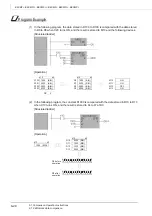
Page 816: ...ut notice When exported from Japan this manual does not require application to the Ministry of Economy Trade and Industry for service transaction permission HEAD OFFICE TOKYO BUILDING 2 7 3 MARUNOUCHI CHIYODA KU TOKYO 100 8310 JAPAN NAGOYA WORKS 1 14 YADA MINAMI 5 CHOME HIGASHI KU NAGOYA JAPAN ...

Reviews: