manualshive.com logo in svg
background image

Application Technique

Safety Function: Actuator Subsystems – Stop Category 1 via 
the PowerFlex 525 and PowerFlex 527 Drives with Safe 
Torque-off

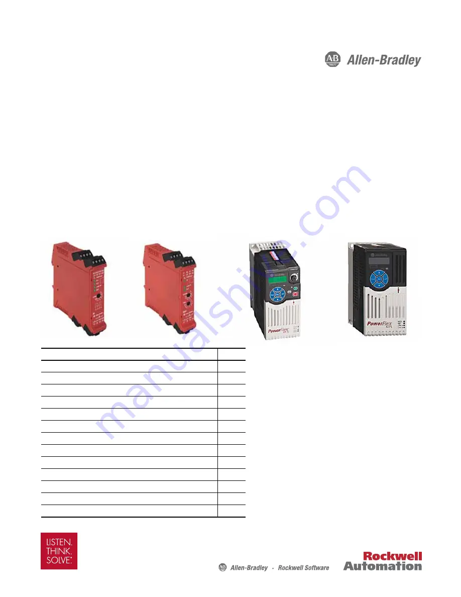
Products: Guardmaster Dual-input Safety Relay, Guardmaster Multifunction-delay Expansion Module, PowerFlex 525 Drive, 
PowerFlex 527 Drive

Safety Rating: CAT. 3, PLd to ISO 13849-1: 2008

Topic

Page

Important User Information

2

General Safety Information

3

Introduction

3

Safety Function Realization: Risk Assessment

3

Stop Safety Functions

4

Safety Function Requirements

4

Functional Safety Description

5

Bill of Material

6

Setup and Wiring

6

Configuration

11

Calculation of the Performance Level

13

Verification and Validation Plan

17

Additional Resources

22

Содержание PowerFlex 525

Страница 1: ... 525 Drive PowerFlex 527 Drive Safety Rating CAT 3 PLd to ISO 13849 1 2008 Topic Page Important User Information 2 General Safety Information 3 Introduction 3 Safety Function Realization Risk Assessment 3 Stop Safety Functions 4 Safety Function Requirements 4 Functional Safety Description 5 Bill of Material 6 Setup and Wiring 6 Configuration 11 Calculation of the Performance Level 13 Verification ...

Страница 2: ...ent liability is assumed by Rockwell Automation Inc with respect to use of information circuits equipment or software described in this manual Reproduction of the contents of this manual in whole or in part without written permission of Rockwell Automation Inc is prohibited Throughout this manual when necessary we use notes to make you aware of safety considerations Labels may also be on or inside...

Страница 3: ...rd switch as in Safety Function Door Monitoring Products SensaGuard GSR DI publication SAFETY AT069 is used as a convenient example of an Input subsystem in this application technique Safety Function Realization Risk Assessment The required performance level is the result of a risk assessment and refers to the amount of the risk reduction to be carried out by the safety related parts of the contro...

Страница 4: ...stem initiates and maintains a stop command for the safety system to stop hazardous motion before a person can reach the hazardous area The stop command cannot be reset until the guard door is closed Prevention of an Unexpected Startup The safety system cannot be reset and hazardous motion cannot be restarted while the guard door is open Once the guard door is closed and the stop command is reset ...

Страница 5: ...ter multifunction delay expansion module is configured to provide a 100 ms delay In the event of an internal fault or a fault signaled via the SWS the Guardmaster multifunction delay expansion module immediately de energizes its safety outputs The PowerFlex drive monitor its STO inputs for valid status and faults The drive monitors its internal safety circuits for valid status and faults The drive...

Страница 6: ... dual input safety relay s safety outputs energize the Guardmaster multifunction delay expansion module energizes its safety outputs and the drive s STO inputs are powered The hazardous motion can then be restarted by pressing a PAC controlled Start button PreventionofanUnexpectedStart up The Guardmaster dual input safety relay cannot be reset while its input device is in a tripped guard door open...

Страница 7: ...the basis of an approach speed of the body or part of the body in our case a hand ISO 13855 defines the approach speed of a hand as 1600 mm per sec Using this value we calculate the access time 762 mm 1600 mm per sec or 476 ms ANSI B11 19 defines the approach speed of a hand as 63 in per sec Using this value we calculate the access time 30 in 63 in per sec or 476 ms OverallSystemStoppingPerformanc...

Страница 8: ...function delay expansion module GSR EMD Guardmaster multifunction delay expansion module delay EMDd PowerFlex 525 drive drive overall system stopping performance less maximum safe coast to stop time 54 ms SG 35 ms GSR DI 35 ms EMD 100 ms EMDd 100 ms drive 324 ms overall system stopping performance time less the estimated maximum safe coast to stop time 476 ms 324 ms 152 ms estimated maximum safe c...

Страница 9: ...y wired to the PowerFlex 525 drive This button is used for normal non safety stops and starts of the system It is also used to start restart the drive after safety related stops once the safety circuit is reset Figure 1 PowerFlex 525 Circuit 24V DC 0V DC COM Typical Safety Input Device 24V DC 0V DC Start Stop Gate control powersupply Gate control circuit Initiate Configured Normal Production Stop ...

Страница 10: ...of this circuit This button is used for normal non safety stops and starts of the system It is also used to start restart the drive after safety related stops once the safety circuit is reset Figure 2 PowerFlex 527 Circuit 24V DC 0V DC COM Typical Safety Input Device 24V DC 0V DC To PAC Digital Common Gate control power supply Gate control circuit Initiate Configured Normal Production Stop Start S...

Страница 11: ...mation about this relay refer to Guardmaster Safety Relay DI Installation Instructions publication 440R IN037 1 Enable Program mode 2 Set Operation mode to 2 Manual Reset IN1 and IN2 or L12 3 Cycle power to store the configuration setting Configure the Guardmaster Multifunction delay Expansion Module Follow these steps to configure the Guardmaster multifunction delay expansion module For more info...

Страница 12: ... Fault status indicator will flash red 2 Set timing mode configuration Turn the Range rotary switch to 1 0 1 to 1 0 second and then turn the Time rotary switch to 1 10 The B1 and IN indicators blink the new setting The PWR Fault status indicator flashes steady green to indicate that the positions are set 3 Cycle power to the unit to store the configuration setting IMPORTANT The configuration must ...

Страница 13: ...gn Environment A detailed description of how to fully configure the PowerFlex 527 drive is beyond the scope of this document For more information about this drive refer to PowerFlex 527 Adjustable Frequency AC Drive User Manual publication 520 UM002 By default the PowerFlex 527 drive provides a coast to stop in response to an STO input This action overrides any other stop type that might be config...

Страница 14: ... the Rockwell Automation SISTEMA library The functional safety data for the PowerFlex 527 drive is from the PowerFlex 527 Adjustable Frequency AC Drive User Manual publication 520 UM002 Logic and Output Subsystems Calculation The PowerFlex 525 drive yields the following results This can be modeled as follows The PowerFlex 527 drive yields virtually the same results The same parts produce the same ...

Страница 15: ...cal safety input device For instance when the PowerFlex 525 drive is used these are the SISTEMA calculations for the safety function Safety related stop function initiated by a safeguard When the PowerFlex 525 drive is used in the safety function Prevention of an unexpected startup the SISTEMA calculations are identical because all of the same components are used Logic Output Subsystem 1 Subsystem...

Страница 16: ...ch achieve their necessary PLr When the PowerFlex 527 drive is used in the safety function Safety related stop function initiated by a safeguard the SISTEMA calculation results are as follows As before when the PowerFlex 527 drive is used in the safety function Prevention of an unexpected start up the calculations are identical because all of the same components are used Each PowerFlex 527 safety ...

Страница 17: ...ocument uses as an example a SensaGuard switch for an input device Notice that in the validation process all of the purposely created faults are created at the input terminals of the Guardmaster dual input safety relay All of the relay s responses to these faults are the same as they would be using any typical input device with OSSD outputs or an electro mechanical input device using the Guardmast...

Страница 18: ...us motion starts and the machine begins to operate 11 Openthe guarded door The safety system must trip The hazardous motionmust stop withintherequiredtime MonitorthestatusindicatorsontheGuardmasterdual input safety relay and Guardmaster multifunction delay expansion module for proper operation Only the PWR Fault status indicator on both devices should be steady green All other status indicators sh...

Страница 19: ...rips immediately The status indicator on the SensaGuard switch blinks red The Guardmaster dual input safety relay IN1 IN2 and OUT status indicators are OFF The Guardmaster multifunction delay expansion module LoginIN and OUT status indicators are OFF 11 Remove the jumper Neither the SensaGuard switch nor the Guardmaster dual input safety relay respond Press and release the Reset button Nothing cha...

Страница 20: ...xternal Start button The hazardous motion must resume 7 While the hazardous motion continues to run jump 0V to the L12 terminal of the Guardmaster multifunction delay expansion module After a second or two the hazardous motion coasts to a stop The Logic IN and OUT status indicators of the Guardmaster multilfunction delay expansion module are off The OUT status indicator of the Guardmaster dual inp...

Страница 21: ... not respond The STO fault remains 10 Cyclepowertothedrive TheSTOfaultiscleared PresstheStartbutton Thehazardous motion starts 11 Repeat steps 1through 10 usingthePowerFlex drive s terminal S2inplace of terminal S1 The system responses must be the same as before Confirmation of Performance The overall systemstopping performance does not exceed 476 ms SensaGuard Switch Guardmaster Dual input Safety...

Страница 22: ...uardmaster multifunction delay expansion module Guardmaster Safety Relays DI DIS SI CI GLP EM and EMD Selection Guide publication 440R SG001 Provides descriptive information about how to select and configure a Guardmaster safety relay PowerFlex 520 Series AdjustableFrequency AC Drive Quick Start Guide publication 520 QS001A Summarizes the basic steps needed to install start up and program the Powe...

Страница 23: ...Rockwell Automation Publication SAFETY AT140A EN P May2015 23 Safety Function Actuator Subsystems Stop Category 1 via the PowerFlex 525 and PowerFlex 527 Drives with Safe Torque off Notes ...

Страница 24: ...Documentation Feedback Your comments will help us serve your documentation needs better If you have any suggestions on how to improve this document complete this form publication RA DU002 available at http www rockwellautomation com literature Rockwell Otomasyon Ticaret A Ş Kar Plaza İş Merkezi E Blok Kat 6 34752 İçerenköy İstanbul Tel 90 216 5698400 For more information on Safety Function Capabil...

Отзывы: