


11-10
1. Measuring Compression Pressure
Service standards
Special tools (Unit: mm)
•
A drop in compression pressure can be used as a guide to determine when the engine should be overhauled.
•
Measure the compression pressure at regular intervals. Keeping track of its transitions can provide a useful tool
for troubleshooting. On new vehicles and vehicles with newly replaced parts, the compression pressure will be
somewhat higher depending on the break-in condition of piston rings, valve seats, etc., but this will return to nor-
mal as the parts wear down.
•
Before inspection, confirm that the engine oil, starter, and battery are in normal condition, and satisfy the following
conditions.
•
Warm up the engine until the coolant temperature reaches approximately 75 to 85
°
C.
•
Turn off the lights and auxiliaries.
•
Place the lever in neutral.
•
Remove the fuse for fuel cut to prevent fuel from being injected
while the engine is cranked using the starter.
CAUTION
• When cranking the engine, never shut off the power sup-
plied to the engine electronic control unit by disconnecting
the engine electronic control unit connector or other similar
methods. If the engine is cranked with the power to the en-
gine electronic control unit shut off, the supply pump will
not be controlled by the electronic control unit, causing the
supply pump to be malfunctioned.
Location
Maintenance item
Standard value
Limit
Remedy
–
Compression pressure
Each cylinder (at 200 rpm)
2,940 kPa
{30 kgf/cm
2
}
1,960 kPa
{20 kgf/cm
2
}
Inspect
Cylinder-to-cylinder pres-
sure difference
–
390 kPa
{4 kgf/cm
2
}
or less
Inspect
Mark
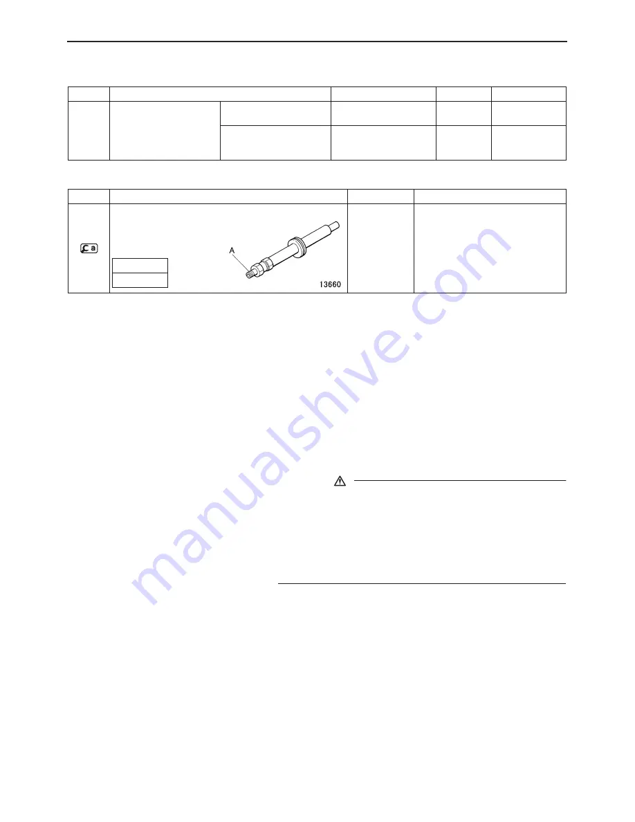
Tool name and shape
Part No.
Application
MH063384
Measuring compression pressure
Compression gauge
adapter
A
M16
×
18
GENERAL INSPECTION AND ADJUSTMENT
Summary of Contents for 6M60-TL
Page 2: ......
Page 8: ...00 00 5 ...
Page 26: ...00 00 23 212340 OutputUnit V OutputUnit OutputUnit ...
Page 27: ...00 24 3 2 2 VCM 3OP input monitor and output monitor VCM 3 VCM 3OP 212341 ...
Page 28: ...00 00 25 3 2 3 MP input monitor VCM 3 MP 212342 ...
Page 45: ...M E M O 11 9 11 ...
Page 51: ...M E M O 11 15 11 ...
Page 52: ...11 16 ROCKER COVER ROCKER BRACKET AND CAMSHAFT ...
Page 60: ...11 24 CYLINDER HEAD AND VALVE MECHANISM ...
Page 67: ...M E M O 11 31 11 ...
Page 83: ...M E M O 11 47 11 ...
Page 89: ...M E M O 11 53 11 ...
Page 97: ...M E M O 11 61 11 ...
Page 103: ...M E M O 11 67 11 ...
Page 104: ...11 68 CRANKSHAFT AND CRANKCASE ...
Page 142: ...M E M O 13A 9 13A ...
Page 152: ...M E M O 13A 19 13A ...
Page 161: ...M E M O 13E 3 13E ...
Page 164: ...13E 6 1 1 Supply pump STRUCTURE AND OPERATION ...
Page 176: ...13E 18 3 Electronic Control Unit Connection Diagram STRUCTURE AND OPERATION ...
Page 177: ...13E 13E 19 ...
Page 212: ...14 14 3 1 Cooling System Flow of Coolant STRUCTURE AND OPERATION ...
Page 220: ...M E M O 14 11 14 ...
Page 236: ...M E M O 14 27 14 ...
Page 255: ...M E M O 15 13 15 ...
Page 273: ...54 4 2 Alternator 24V 50A STRUCTURE AND OPERATION ...
Page 276: ...54 54 7 3 Circuit diagram ...
Page 308: ...M E M O 61 3 61 ...
Page 309: ...61 4 1 Air Compressor STRUCTURE AND OPERATION ...
Page 318: ...M E M O 61 13 61 ...
Page 319: ...61 14 AIR COMPRESSOR 154 cm3 154 mL ...
Page 322: ...M E M O 61 17 61 ...
Page 323: ...61 18 AIR COMPRESSOR 319 cm3 319 mL ...
Page 326: ...M E M O 61 21 61 ...
Page 327: ...61 22 AIR DRYER ...


