


54-26
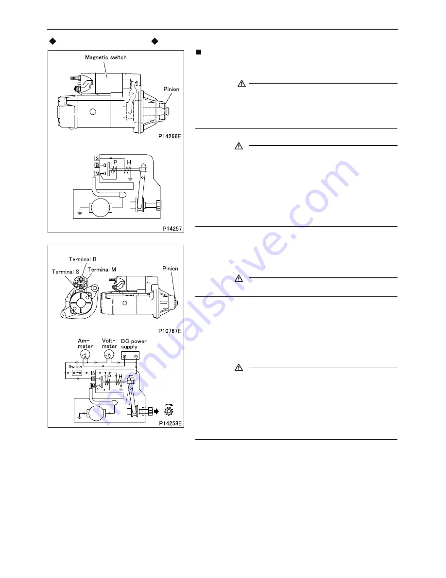
Inspection after assembly
Inspection: Performance and pinion gap
•
After assembling the starter, perform inspections with current
supplied to it.
WARNING
• When the starter is energized, the pinion will spring out and
rotate. Be careful not to touch it with your hands.
• The magnetic switch may become very hot during inspec-
tions. Be careful when touching it.
CAUTION
• Do not energize the pull-in coil P for longer than 10 sec-
onds, and do not energize the holding coil H for longer than
30 seconds. If these periods are exceeded, the coils may
overheat and burn out.
• When current is supplied to the starter, a large current (100
A or higher) will flow. For inspection purposes, booster ca-
bles or similarly thick cables must therefore be used. Also,
it is important to ensure that all connections are secure.
(1) Performance test
•
Connect the starter as illustrated.
•
Set the voltage to 23 Volts DC.
CAUTION
• The voltage applied must not exceed 24 V.
•
The following operations are performed with current supplied to
the starter. Thus, the entire test (consisting of measurement of
the current flowing through the starter and measurement of the
starter’s rotational speed) must be completed within 30 seconds.
•
Turn ON the switch to supply current to the starter. The pinion
will spring out and rotate.
CAUTION
• When the switch is turned ON, the pull-in coil P and holding
coil H are both energized. When the large current from the
DC power supply flows from terminal B to terminal M, the
supply of current to the pull-in coil P is cut; only the holding
coil H remains energized. To prevent the holding coil from
burning out, it is essential to complete all operations within
30 seconds.
•
Measure the current and the starter’s rotational speed. To
measure the rotational speed, shine a stroboscope on the pin-
ion.
•
Turn OFF the switch to de-energize the starter.
•
If either measurement is out of specification, disassemble and
inspect the starter again.
#930 STARTER
Summary of Contents for 6M60-TL
Page 2: ......
Page 8: ...00 00 5 ...
Page 26: ...00 00 23 212340 OutputUnit V OutputUnit OutputUnit ...
Page 27: ...00 24 3 2 2 VCM 3OP input monitor and output monitor VCM 3 VCM 3OP 212341 ...
Page 28: ...00 00 25 3 2 3 MP input monitor VCM 3 MP 212342 ...
Page 45: ...M E M O 11 9 11 ...
Page 51: ...M E M O 11 15 11 ...
Page 52: ...11 16 ROCKER COVER ROCKER BRACKET AND CAMSHAFT ...
Page 60: ...11 24 CYLINDER HEAD AND VALVE MECHANISM ...
Page 67: ...M E M O 11 31 11 ...
Page 83: ...M E M O 11 47 11 ...
Page 89: ...M E M O 11 53 11 ...
Page 97: ...M E M O 11 61 11 ...
Page 103: ...M E M O 11 67 11 ...
Page 104: ...11 68 CRANKSHAFT AND CRANKCASE ...
Page 142: ...M E M O 13A 9 13A ...
Page 152: ...M E M O 13A 19 13A ...
Page 161: ...M E M O 13E 3 13E ...
Page 164: ...13E 6 1 1 Supply pump STRUCTURE AND OPERATION ...
Page 176: ...13E 18 3 Electronic Control Unit Connection Diagram STRUCTURE AND OPERATION ...
Page 177: ...13E 13E 19 ...
Page 212: ...14 14 3 1 Cooling System Flow of Coolant STRUCTURE AND OPERATION ...
Page 220: ...M E M O 14 11 14 ...
Page 236: ...M E M O 14 27 14 ...
Page 255: ...M E M O 15 13 15 ...
Page 273: ...54 4 2 Alternator 24V 50A STRUCTURE AND OPERATION ...
Page 276: ...54 54 7 3 Circuit diagram ...
Page 308: ...M E M O 61 3 61 ...
Page 309: ...61 4 1 Air Compressor STRUCTURE AND OPERATION ...
Page 318: ...M E M O 61 13 61 ...
Page 319: ...61 14 AIR COMPRESSOR 154 cm3 154 mL ...
Page 322: ...M E M O 61 17 61 ...
Page 323: ...61 18 AIR COMPRESSOR 319 cm3 319 mL ...
Page 326: ...M E M O 61 21 61 ...
Page 327: ...61 22 AIR DRYER ...


