


Page 6-3
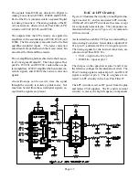
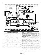
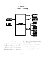
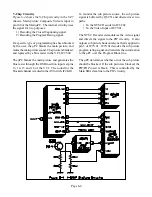
Overall Control Circuitry
The µPC controls the TV’s circuitry mainly through
three I
2
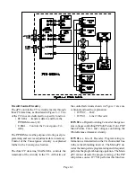
C data lines, as illustrated in Figure 6-3. Two
of the I
2
C lines are dedicated to a specific function:
• EE SDA … transfers data to and from the
E
2
PROM memory IC.
• C-SDA … Controls the Convergence Cir-
cuitry
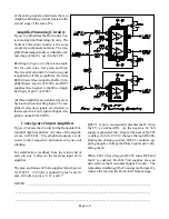
The E
2
PROM serves the purpose of storing user pro-
gramming and service adjustment data in memory.
Control of the Convergence circuitry is explained
further in the Convergence Section.
The third I
2
C data line, MAIN-SDA, controls the
remainder of the circuitry in the TV. All but two of
the controlled circuits shown in Figure 3 are con-
ventional and need no explanation:
• IC2Y02 … DAC
• IC7V01 … Line 21 Decoder
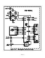
IC2Y02 is a Digital to Analog Converter that gener-
ates voltages controlling PIP Sub Picture Color, POP
Main Picture Color, and voltages controlling the
White Balance (Gamma) circuitry.
IC7V01 is a Line 21 Decoder. Program rating in-
formation is transmitted on the 21st horizontal line
in the vertical blanking interval. The Main µPC de-
codes the main picture program rating and if required,
performs the program blocking operation. The Main
µPC cannot decode the program rating of the PIP
sub picture source. IC7V01 performs this function.
Summary of Contents for VS-45605
Page 11: ...Page 1 8 ...
Page 25: ...Page 3 10 ...
Page 27: ...Page 4 2 ...
Page 31: ...Page 4 6 ...
Page 33: ...Page 4 8 ...
Page 55: ...Page 8 8 ...
Page 57: ...Page 7 2 ...
Page 69: ...Page 9 2 ...


