


Page 4-1
Section 4
Convergence Circuitry
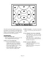
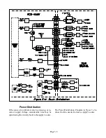
The Convergence Correction Circuitry in the VZ7
chassis is digital. Figure 4-1 illustrates a Basic Block
Diagram of the circuit. Horizontal and vertical pulses
are applied to a Convergence Correction Generator.
The Correction Generator produces Horizontal and
Vertical Correction signals for each CRT, Red, Green
and Blue. The Correction Signals are not analog
waveforms, but are Serial Digital Signals.
The signals are applied to Digital to Analog Con-
verters to produce the analog waveforms required
to drive the Sub Coils in the Deflection Yokes. The
signals are then amplified and applied to their respec-
tive Yoke Sub Coils.
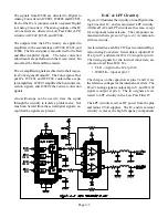
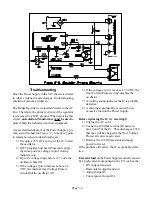
Overall Convergence Circuitry
Figure 4-2 shows a simplified diagram of the Over-
all Convergence Circuitry. IC800 is the Convergence
Correction Waveform Generator. Horizontal pulses
are derived from the Horizontal Output stage cir-
cuitry, and vertical pulses from the V-Pump terminal
on the Vertical Output IC, IC451.
The horizontal and vertical pulses are buffered by
IC803, on the PCB-CONV, and then directed to
IC800. IC803 is comprised of two D-type Flip Flops
providing clean precisely timed output pulses. The
internal circuitry in IC800, uses the pulses from IC803
to generate the Convergence Correction signals, in a
Serial Digital format.
Summary of Contents for VS-45605
Page 11: ...Page 1 8 ...
Page 25: ...Page 3 10 ...
Page 27: ...Page 4 2 ...
Page 31: ...Page 4 6 ...
Page 33: ...Page 4 8 ...
Page 55: ...Page 8 8 ...
Page 57: ...Page 7 2 ...
Page 69: ...Page 9 2 ...


