햲
Locate and correct the cause of the error and allow the servo amplifier, the servo motor and
the regenerative braking unit to cool down for at least 30 minutes before resetting the alarm
and restarting the system for normal operation.
햳
Switch on the RES signal.
햴
To reset the alarm click on the Alarm Reset button in the alarm display window in MR
Configurator. You can also reset the alarm by pressing the STOP/RESET button on the HMI
control unit.
햵
0: OFF
1: ON
NOTE
The output signal ALM is activated when an error or alarm signal is triggered.
NOTE
Please see the instruction manual for more detailed descriptions of the alarm messages and
warnings.
Alarms and Warning Messages
Appendix
A - 42
MITSUBISHI ELECTRIC
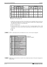
Display
Warning
W
a
rn
ing
m
essages
A90
Home position return incomplete
A92
Battery cable disconnected
A96
Home position return error
A98
Software limit warning
A99
Stroke limit warning
A9A
Option unit input data error
A9F
Battery warning
AE0
Regenerative system overload warning
AE1
Overload warning 1
AE3
Absolute position counter error
AE6
Server emergency off warning
AE8
Cooling fan too slow
AE9
Main circuit off
AEC
Overload warning 2
AED
Output wattage exceeded
Table A-4:
Warning messages
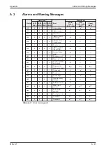
Display
Alarm Code
Error
Alarm Reset
ACD3
(Bit 3)
ACD2
(Bit 2)
ACD1
(Bit 1)
ACD0
(Bit 0)
Power
Supply
OFF
ON
MR-
Configurator/
HMI
Reset
(RES)
Alar
ms
A52
0
1
0
1
Excessive discrep-
ancy error
✔
✔
✔
A61
0
1
0
1
Operation alarm
✔
✔
✔
A8A
0
0
0
0
Serial communica-
tion timeout
✔
✔
✔
A8E
0
0
0
0
Serial communica-
tion error
✔
✔
✔
888
0
—
—
—
Watchdog
✔
—
—
Table A-3: Error messages (2)

