background image

4.3.2

Dog mode home position return

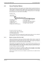
In this mode, instead of the encoder Z-phase(Fig. 4-6), the DOG signal is used to switch from
“home position return speed” PC04 to “creep speed” PC05. You can use parameter PD16 “prox-
imity dog detection polarity” to specify whether a logical “1” or a logical “0” should be identified as
an active DOG signal.

As in

above, the physical home position can be shifted in relation to the home (zero) position

of the encoder (Z-phase) with PC06 “home position offset (shift)”. In addition to this you can also
set a non-zero coordinate for the home position with PC07.

Conditions for the proximity dog signal:

The proximity dog signal (DOG) must fulfill the following conditions to ensure that the Z-phase of
the encoder is detected during the activation period of the DOG signal:

Positioning with Digital Inputs

Home Position Return

MR-J3-T

4 - 19

L

1

60

2

L1 = Length of the DOG signal in [mm]
V = Home position return speed in [mm/min]
t

d

= Deceleration time in [s]

L

2

2

폷 욼

S

L2 = Length of the DOG signal in [mm]

S = Distance for one rotation of the motor in [mm]

V

t

d

Summary of Contents for MR-J3-T

Page 1: ...Servo Amplifier Quick Start Manual MR J3 T Servo Amplifier With Point Table Positioning Point to Point Positioning Art No xxxxxx 21122007 Version A MITSUBISHI ELECTRIC MITSUBISHI ELECTRIC INDUSTRIAL AUTOMATION ...

Page 2: ......

Page 3: ... or one of our official distributors see back cover You can find up to date information and answers to frequently asked questions on our website www mitsubishi automation com MITSUBISHI ELECTRIC EUROPE B V reserves the right to make technical changes to the products or this manual at any time without prior notice December 2007 MITSUBISHI ELECTRIC EUROPE B V ...

Page 4: ......

Page 5: ...Quick Start Manual MR J3 T Servo Amplifier with Integrated Point Table Positioning Art No xxxxxx Version Changes Additions Corrections A 10 2007 pdp First Edition ...

Page 6: ......

Page 7: ...ns that are not covered in this Quick Start Manual 쎲 Communication via a serial port for controlling point table positioning 쎲 Positioning control in BCD format with the optional MR DS60 digital switch 쎲 Amplifier controller circuit settings and auto tuning functions Safety Instructions To ensure safe and proper installation of the equipment please also observe the instructions and safety precauti...

Page 8: ...ning off Automatic Input Signal Activation 4 14 4 3 Home Position Return 4 15 4 3 1 Dogless Z phase reference mode 4 15 4 3 2 Dog mode home position return 4 19 4 4 Configuration for Positioning 4 23 4 4 1 Importing and exporting point tables 4 26 4 5 Functional Test of Digital Input Positioning 4 28 5 Positioning via a CC Link Network 5 1 Additional Connections 5 31 5 2 CC Link Communication Sett...

Page 9: ...cted amplifier Example HF KP13 motor for the MR J3 10T servo amplifier 쎲 MRZJW3 SETUP221E Version C0 of the MR Configurator setup software package 쎲 MR J3USBCBL3M USB cable for connecting your PC notebook with the servo amplifier 쎲 MR PWS1CBL M A1 L motor connection cable 쎲 MR J3ENCBL M A2 L rotary encoder cable 쎲 MR J2CMP2 connector for CN6 I O signal connector 쎲 Power supply cables conforming to...

Page 10: ...eries SC 09 쎲 The GX IEC Developer programming software package for configuration of the data com munications settings NOTE This Quick Start Manual describes the installation and setup of a typical servo system con sisting of an MR J3 10T servo amplifier single phase 230V 100W and an HF KP13 ser vo motor Note that the specifications of this sample system may differ from those of your configuration...

Page 11: ...t side of the MR J3 T housing 햳 Position the MR J3 D01 extension over the upper and lower mounting points 1 on the ser vo amplifier then press the extension into place so that the lugs click into position in the up per and lower mounting points 2 This also connects the extension to the amplifier via con nector CN7 on the amplifier 햴 Fasten the extension securely to the servo amplifier with the M4 ...

Page 12: ...rse order To release the retai ning clips press the retaining tabs marked Push inwards and pull the extension out to the side Installing the MR J3 D01 Extension Installing the Equipment 2 4 MITSUBISHI ELECTRIC Fig 2 2 Fastening screw dimensions for extension MR J3 D01 ...

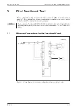
Page 13: ...g properly NOTE You can also use the optional MR PRU 03 HMI control terminal for performing initial tests and setting the amplifier s parameters For further details see the MR J3 T series instruction manual 3 1 Minimum Connections for the Functional Check First Functional Test Minimum Connections for the Functional Check MR J3 T 3 5 Fig 3 1 Wiring diagram for minimum configuration without control ...

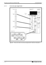
Page 14: ...nections for the Functional Check First Functional Test 3 6 MITSUBISHI ELECTRIC Fig 3 2 Power and control connector pin assignments for minimum configuration Power terminals Servo amplifier MR J3 첸T USB port I O extension MR J3 D01 Connector CN2 ...

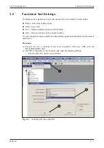
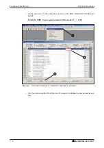
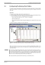
Page 15: ...e end limit switch You can configure the servo amplifier to activate these signals automatically when the power is switched on Procedure 햲 Connect the PC notebook to the servo amplifier s USB port CN5 with the MR J3USBCBL3M cable 햳 Start MR Configurator on the computer and make the following settings Select the MR J3 T series servo amplifier First Functional Test Functional Test Settings MR J3 T 3...

Page 16: ... Parameter PD01 Input signal automatic ON selection 1 1C04 Turn the servo amplifier off and then turn it on again to initialise the new parameter set ting Functional Test Settings First Functional Test 3 8 MITSUBISHI ELECTRIC Fig 3 4 Parameter settings for automatic input signal activation ...

Page 17: ...ite All button Make sure that the Aux Func value in every line is left at the default factory setting 0 to ensure that selecting a position value in the table does not inadvertently activate any subse quent table entries NOTES In the factory default settings the absolute value command system for the target positions is activated with parameter PA01 STY When this system is active all target positio...

Page 18: ...ockwise 쎲 REVERSE clockwise NOTES Home position return is not possible in test mode when using MR Configurator use the jog function to move to the starting position You can set the rotation direction in single step feed mode with parameter PA14 3 4 1 Selecting point table position entries Procedure 햲 Select Single step Feed in the Test menu 햳 To select a position enter its point table line number ...

Page 19: ...described in chapter 3 1 were performed with a minimum connection configuration For the full range of standard functions you now need to make additional power supply and control terminal connections on the CN6 and CN10 terminal blocks as shown below in Figs 4 1 and 4 2 Positioning with Digital Inputs Additional Connections MR J3 T 4 11 Fig 4 1 Single phase power connections for the MR J3 T amplifi...

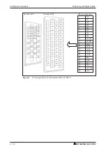
Page 20: ...UBISHI ELECTRIC 1 DI0 2 DI1 3 DI2 4 DI3 5 DI4 6 DI5 7 DI6 8 DI7 13 DICOM 14 DICOM 21 SON 22 ACD0 23 ACD1 24 ACD2 25 ACD3 26 RES 32 MD0 35 ST1 36 ST2 37 DOCOM 49 INP Connector CN6 Connector CN10 CN10 pin assignments Fig 4 2 Pin assignments of connectors CN6 and CN10 ...

Page 21: ...1 and the amplifier is deactivated when there is no EMG signal if it is configured accordingly see chapter 3 2 Positioning with Digital Inputs Additional Connections MR J3 T 4 13 Fig 4 3 Connection of the control terminals with PNP logic source logic 24V DC 10 150mA 햲 24V DC EMG OFF Proximity dog Forward stroke end Reverse stroke end max 10m max 10m 24V DC 10 800mA 햲 24V DC Point table selection S...

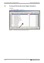
Page 22: ...put Signal Activation Procedure 햲 Reset parameter PD01 to a value of 0 Turning off Automatic Input Signal Activation Positioning with Digital Inputs 4 14 MITSUBISHI ELECTRIC Fig 4 4 Switching off automatic input signal activation ...

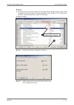
Page 23: ...ical home position exactly matches the Z phase of the encoder It is thus almost always necessary to enter an offset shift with parameter PC06 After activation of the forward start command ST1 or reverse ST2 the home position return is initiated by parameter PC04 home position return speed When the Z phase signal from the encoder is registered the servo motor brakes to a halt After this a precise r...

Page 24: ... to the physical coor dinate system PC02 햲 ZTY Home position re turn mode Selects the home position return mode A Dogless Z phase reference mode PC03 햲 ZDIR Home position re turn direction 0 Incrementing counting of encoder pulses 1 Decrementing counting of encoder pulses PC04 ZRF Home position re turn speed Sets home position return speed until first detection of the Z phase in rpm PC05 CRF Creep...

Page 25: ... position return at 200 rpm in the direction in which the encoder pulses are counted incrementally Parameter settings Positioning with Digital Inputs Home Position Return MR J3 T 4 17 Fig 4 6 Relevant parameter settings for example 1 Parameter settings for example Fig 4 7 Values shown when the home position return has been completed correctly ...

Page 26: ...vant parameter settings for example 2 The offset is entered with param eter PC06 Parameter settings for example Fig 4 9 Values shown when the home position return has been completed correctly Following completion of the home position return The servo motor has travelled to the specified home position The home position of the encoder has been exceeded by the value of PC06 3 000 µm For the motor con...

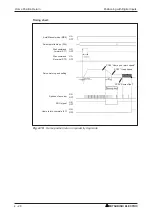
Page 27: ...he encoder Z phase with PC06 home position offset shift In addition to this you can also set a non zero coordinate for the home position with PC07 Conditions for the proximity dog signal The proximity dog signal DOG must fulfill the following conditions to ensure that the Z phase of the encoder is detected during the activation period of the DOG signal Positioning with Digital Inputs Home Position...

Page 28: ... ON OFF Select point table no DI0 Start command Forward ST1 ON OFF Start command Reverse ST2 ON OFF Servo motor speed setting Z phase of encoder ON OFF DOG signal ON OFF Home return complete ZP ON OFF Fig 4 10 Home position return in proximity dog mode PC05 Creep speed PC04 Home pos return speed PC06 Home offset ...

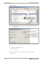
Page 29: ...menting counting of encoder pulses 1 Decrementing counting of encoder pulses PC04 ZRF Home position re turn speed Sets home position return speed until first detection of the Z phase in rpm PC05 CRF Creep speed Speed for precise movement to home position in rpm PC06 ZST Home position offset shift Distance between the encoder home position Z phase and the physical home position in µm Does not chang...

Page 30: ... 11 Relevant parameter settings for the example The home position value is en tered with PC07 Parameter settings for example Fig 4 12 Values shown when the home position return has been completed correctly Following completion of the home position return The servo motor has travelled to the encoder home position which is also the machine s physical home position How ever this position corresponds ...

Page 31: ... the amplifier power off and on again Positioning with Digital Inputs Configuration for Positioning MR J3 T 4 23 Digital Input Signals Selected Point Table Entry DI7 DI6 DI5 DI4 DI3 DI2 DI1 DI0 0 0 0 0 0 0 0 1 1 0 0 0 0 0 0 1 0 2 0 0 0 0 0 0 1 1 3 0 0 0 0 0 1 0 0 4 1 1 1 1 1 1 1 0 254 1 1 1 1 1 1 1 1 255 Table 4 3 Selection of point table entries with digital input signals No Code Function Descrip...

Page 32: ...ositions are entered using the incremental system it is not possible to change the rotation direction via the point table In this mode the rotation direction can only be changed with the start commands ST1 ST2 Configuration for Positioning Positioning with Digital Inputs 4 24 MITSUBISHI ELECTRIC Fig 4 13 Effective range of the position values with the sample settings Min absolute value 9999 99 Max...

Page 33: ...for the current table line and continuing to the next table line This option should only be used when multiple positioning steps are performed automatically without changes in the input signals 쎲 The button Insert inserts a new line above the selected table line Delete deletes the se lected line 쎲 The Verify function checks whether the positioning table in MR Configurator matches the table stored ...

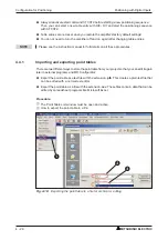
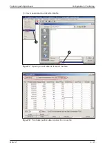
Page 34: ...re two different ways to store the point table from your project so that you can edit it again later in external programs and MR Configurator 쎲 Export the point table as a text file with the extension ptb This creates a plain text file that can be edited with a normal text editor 쎲 Export the point table as a file with the extension csv These files contain data that can be edited by spreadsheet pr...

Page 35: ...port a point table data file Positioning with Digital Inputs Configuration for Positioning MR J3 T 4 27 Fig 4 17 Opening a point table file to import the data Fig 4 18 Point table position data imported from a csv file ...

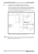
Page 36: ...ontroller Note that the FX Simulation Box used in this setup can set a maximum of 14 digital inputs NOTE The test setup shown above does not use any safety features for the tests EMG OFF You should thus only use this setup in a controlled test environment where errors cannot cause any danger for personnel or equipment Functional Test of Digital Input Positioning Positioning with Digital Inputs 4 2...

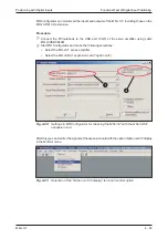
Page 37: ...lections Select the MR J3 T series amplifier Select the MR J3 D01 expansion card option unit After this you can monitor the signals of the expansion card with the option Option unit I F display in the Monitor menu Positioning with Digital Inputs Functional Test of Digital Input Positioning MR J3 T 4 29 Fig 4 20 Settings in MR Configurator for checking the MR J3 T with the MR J3 D01 expansion card ...

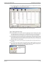
Page 38: ...Functional Test of Digital Input Positioning Positioning with Digital Inputs 4 30 MITSUBISHI ELECTRIC Fig 4 22 The Option unit I F display terminal monitoring window ...

Page 39: ...itional Connections In addition to the minimum configuration described in chapter 3 1 you also need to connect the CC Link cable and the cabling for connector CN6 for this mode Positioning via a CC Link Network Additional Connections MR J3 T 5 31 Fig 5 1 Connections for operating the servo amplifier via a CC Link network 1 phase 200 230V AC Servo motor Motor Encoder Encoder cable Alarm EMG OFF OFF...

Page 40: ...n the CC Link network The required ohmage of the resistor depends on the cable length please check the version V1 10 specifications for details Additional Connections Positioning via a CC Link Network 5 32 MITSUBISHI ELECTRIC Fig 5 2 Connections between the servo amplifier and the CC Link master module CC Link Master module e g QJ61BT11N MR J3 T ...

Page 41: ... in a System Q con troller platform with a Q02H CPU Procedure 햲 Set the number of reserved stations 햳 Set the station address max value 64 Positioning via a CC Link Network CC Link Communication Settings MR J3 T 5 33 Fig 5 3 Correct position of switch S1 for setting the number of reserved stations S1 Factory default setting 1 reserved station 2 reserved stations Fig 5 4 Set switches x1 and x10 to ...

Page 42: ...tioning are described in chapters 4 2 through 4 4 Please check that these settings have been made correctly before proceeding CC Link Communication Settings Positioning via a CC Link Network 5 34 MITSUBISHI ELECTRIC Fig 5 5 Mode switch setting for the network data rate Mode Baud rate ...

Page 43: ...to integrate the servo amplifier in your project Procedure How to open an existing project in GX IEC Developer 햲 Select Network in the project directory tree in the left window 햳 Select CC Link in the Network Parameter box 햴 This opens the window Network parameters Setting the CC Link list where you can now enter the settings shown in Fig 5 6 Positioning via a CC Link Network CC Link Communication...

Page 44: ...tablished successfully the L RUN SD und RD status LEDs on the servo amplifier will light up CC Link Communication Settings Positioning via a CC Link Network 5 36 MITSUBISHI ELECTRIC Fig 5 7 This configuration also enables exchange of data words PLC Servo Amplifier Servo Amplifier PLC PLC I Os Registers Signals PLC I Os Registers Signals Y100 RYn0 SON X100 RXn0 RD Y101 RYn1 ST1 X101 RXn1 INP Y102 R...

Page 45: ...ioning After this you can then test the correct operation of the servo system with the PLC program Procedure 햲 Activate monitoring mode 햳 Select Entry Data Monitor in the Online menu 햴 Enter the individual remote I Os to be set or monitored Positioning via a CC Link Network Testing the Servo Amplifier via CC Link MR J3 T 5 37 Fig 5 8 The Entry Data Monitor window where you can set remote I Os to t...

Page 46: ...ble entry no 2 CN10 3 DI2 RYnC DI Point table entry no 3 CN10 4 DI3 RYnD DI Point table entry no 4 CN10 5 DI4 RYnE DI Point table entry no 5 CN10 6 DI5 RY n 2 3 DI Point table entry no 6 CN10 7 DI6 RY n 2 4 DI Point table entry no 7 CN10 8 DI7 RY n 2 5 DI Point table entry no 8 CN10 13 DICOM Connection for an external power supply for the digital control termi nals Negative connection for source i...

Page 47: ...rn direction 0 Incrementing counting of encoder pulses 1 Decrementing counting of encoder pulses PC04 ZRF Home position re turn speed Sets home position return speed until first detection of the Z phase in rpm PC05 CRF Creep speed Speed for precise movement to home position in rpm PC06 ZST Home position offset shift Distance between the encoder home position Z phase and the physical home position ...

Page 48: ...A17 0 0 0 0 Board error A19 0 0 0 0 Memory error 2 Flash ROM A1A 0 1 1 0 Incorrect servo motor A20 0 1 1 0 Encoder error 2 A24 1 1 0 0 Main circuit error A25 1 1 1 0 Absolute position lost erased A30 0 0 0 1 Regenerative braking overload 햲 햲 햲 A31 0 1 0 1 Overspeed A32 0 1 0 0 Overcurrent A33 1 0 0 1 Overvoltage A35 1 1 0 1 Input frequency too high A37 1 0 0 0 Parameter error A45 0 0 1 1 Main circ...

Page 49: ...g Messages Appendix A 42 MITSUBISHI ELECTRIC Display Warning Warning messages A90 Home position return incomplete A92 Battery cable disconnected A96 Home position return error A98 Software limit warning A99 Stroke limit warning A9A Option unit input data error A9F Battery warning AE0 Regenerative system overload warning AE1 Overload warning 1 AE3 Absolute position counter error AE6 Server emergenc...

Page 50: ...nications 5 35 5 37 H Home position return 4 15 I Installation Hardware 2 3 M Minimum connections 3 5 MR Configurator functional check 3 10 P Parameter Quick reference 4 21 Pin assignments 3 6 Point table configuring 3 9 Point table positioning 4 11 Preparations 1 1 Positioning Settings 4 23 via a CC Link network 5 31 with digital inputs 4 11 Positioning table exporting 4 26 importing 4 26 Positio...

Page 51: ......

Page 52: ...jer Electronics Eesti OÜ Pärnu mnt 160i Phone 372 0 6 51 81 40 Fax 372 0 6 51 81 49 Beijer Electronics OY Jaakonkatu 2 Phone 358 0 207 463 500 Fax 358 0 207 463 501 UTECO A B E E 5 Mavrogenous Str Phone 30 211 1206 900 Fax 30 211 1206 999 MELTRADE Ltd Fertő utca 14 Phone 36 0 1 431 9726 Fax 36 0 1 431 9727 EUROPEAN REPRESENTATIVES Beijer Electronics SIA Vestienas iela 2 Phone 371 0 784 2280 Fax 37...

Reviews: