background image


8

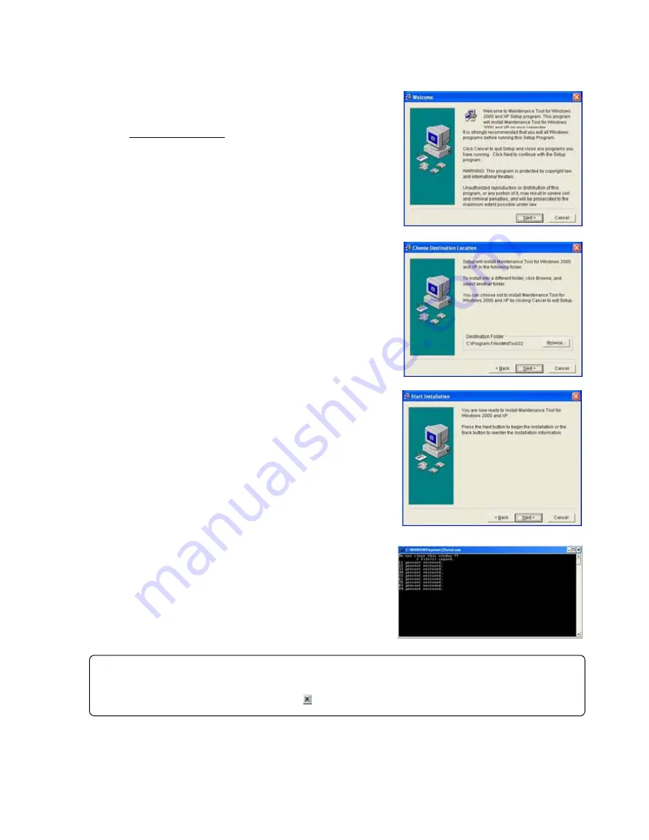
Step 2) Setting up the Maintenance Tools


Set up the application of this 

Maintenance Tools. Please read the guide shown on the screen carefully 

to proceed the setting up.


(1) Starting the setup program 

1) Start MntToolE.EXE. 

Execute 

“MntToolE.EXE”

 located in   

SetUp ¥2_MNTTOOL folder of CD-ROM.   
Double clicking on 

“MntToolE.EXE”

 with the explorer 

displays “Welcome” screen. Please confirm the caution 
shown on the screen before setting up.   

2) Confirm the display contents, and select [

Next

] button. 

If no problem was found on the content, click [

Next

] button. 

* To stop setting up, click on [

Cancel

] button. 


(2) Confirming the Installation folder 

1) Confirm the installation folder and select [

Next

] button. 

Confirm the folder on which this program should be installed. 
To change the installation folder (C drive only), 
Use [

Browse

] button. After confirming the installation 

folder, click on [

Next

] button. 

* Clicking on [

Cancel

] button stops installation procedure. 


(3) Confirming the installation start 

1) Confirm the starting and select [

Next

] button. 

Clicking on [

Next

] button starts installation. 

* Clicking on [

Cancel

] button stops installation. 


(4) During installation, a command prompt like the one shown 

  on the right appears as the process is performed. 


Setup may take up to three minutes to complete. 


Caution: 

During Database setting, the process may be observed as stopped for a while. However, it is still under
operation internally. Wait for some time until "Press any key to continue - - - -" appears without doing anything.
*Do not stop the set up procedure by pressing   at the upper right of the screen. 

Summary of Contents for MN Converter

Page 1: ...Control 47 3 11 Free contact of indoor unit 49 3 12 Remote error notification 51 3 13 Setting and Monitoring DIDO AI PI Controllers 77 4 Off Line Monitor Operating Method 4 1 Off Line Monitor Screen Transfer 113 4 2 Function Chart 114 4 3 Operation Monitor 115 4 4 System Information 119 4 5 Monitoring of Pre error Data 120 4 6 Function common for each screen 121 4 7 Offline Analyze on Wide area ac...

Page 2: ...s conducting various monitoring and setting from the Maintenance Tool MN Converter CMS MNG E RS 232C USB 1 Foreword MN Converter RS 232C cross M NET M NET Maintenance Tools PC To use the maintenance tool via G 50A Network license registration for the G 50A to be used is necessary Purchasing the license No for each G 50A to be used conduct the license registration through the Web browser http IP ad...

Page 3: ...ter CMS MNF B M NET RS 232C straight RS 232C MN Converter Maintenance Tools PC MODEM MODEM Public network MN Converter CMS MNG E USB M NET M NET Maintenance Tools PC NOTE To connect to the MN Converter via USB the USB serial driver must be installed on the Maintenance Tools PC Refer to 1 3 5 NOTE You cannot connect to the MN Converter CMS MNG E via RS 232C and USB at the same time Doing so may res...

Page 4: ...Provider2 Mail server SMTP POP SMTP Mail server Mail server E mail E mail NOTE To use the E mail connection mode the version of G 50A should be above 2 60 When using E mail connection mode the local G 50A is required to be initially set with Maintenance Tool and the mail address by the G 50A initial setting tool For each mail address it is required to obtain and set an exclusive one To transmit ma...

Page 5: ...nditioning system of the customer desired to be accessed Remote access method LAN Accessing by directly connecting Maintenance Tool PC and G 50A with LAN WAN Dialup Accessing by dialup connection to G 50A via public network E mail Accessing by E mail communication to G 50A via mail server Modem MN Converter Accessing by connecting Modem to MN Converter via public telephone circuit After the online...

Page 6: ...re Serial port 1 RS 232C serial port Used when connecting via MN converter USB port 1 USB port Used when connecting via MN converter CMS MNG E 4 LAN port 1 LAN port 10BASE T or faster 3 Optical drive 1 CD ROM CD RW or DVD drive Used when installing the Maintenance Tool to a PC Pointing device Mouse or track ball or any other pointing device 1 About OS Fundamentally it corresponds to OS of each cou...

Page 7: ... 232C is to be straight cable in this case For detail please see Installation Manual annexing of MN Converter CMS MNF CMS MNF B CMS MNG E The power consumption factor of the M NET circuitry of CMS MNG E is 1 5 equivalent to 1 5 Indoor unit 2 In case of routing via G 50A G 50A personal computer LAN cable Straight and HUB A dial up router is required for remote communication For the dial up router t...

Page 8: ...cessing progresses to 100 the screen in the right will be displayed Clicking on OK resets PC automatically Please carry out STEP2 after PC s starting Caution For setting up be sure to practice 2 steps in order Otherwise Maintenance Tools will not operate normally Before setting up be sure to login with the login name authorized as administrator Request Before Setting up the MSDE restart your compu...

Page 9: ...button Confirm the folder on which this program should be installed To change the installation folder C drive only Use Browse button After confirming the installation folder click on Next button Clicking on Cancel button stops installation procedure 3 Confirming the installation start 1 Confirm the starting and select Next button Clicking on Next button starts installation Clicking on Cancel butto...

Page 10: ...on to close the screen 6 Confirming the completion of Maintenance Tools setup 1 Select Finish button Click on Finish button on the Installation Complete screen After completing installation restart your computer Keep the CD ROM used with you carefully Caution After installing Maintenance Tools be sure to restart your computer ...

Page 11: ... program Refer to 1 3 3 Uninstalling the Maintenance Tool Step 3 Upgrade the Maintenance Tool Execute MntToolE EXE located in VerUp 1_MNTTOOL_UPDATE folder of CD ROM Double clicking on MntToolE EXE The Maintenance Tool program version upgrading procedure is the same as new setup Refer to 1 3 1 Step 2 Setting up the Maintenance Tool Caution For setting up be sure to practice 3 steps in order Otherw...

Page 12: ...s 4 Ending the Add Remove Programs After ending the deletion of application end Add Remove Programs 1 3 4 Change of computer name on PC Do not change the computer name after the Maintenance Tool has been setup Maintenance Tool will not run properly if changed and may require the OS to be installed again 1 3 5 USB Serial driver installation To connect the Maintenance Tool to the MN Converter CMS MN...

Page 13: ...s is not a problem Simply click Continue Anyway 4 Installation begins and the window shown on the right appears denoting that USB Serial Converter CMS MNG installation has ended Click Finish 5 Next the window shown on the right appears Repeat steps 2 to 4 NOTE This warning only relates to testing of the Windows logo and does not affect operation ...

Page 14: ...ow shown on the right appears and USB Serial Port CMS MNG installation ends Click Finish This completes USB serial driver CMS MNG installation Check that the driver is running correctly in the Device Manager window ...

Page 15: ...ata obtained by the maintenance tool counts for 2G bite maximum When the remaining storage capacity is insufficient at starting Warning Screen will appear In this case move to OFF Line Screen to delete unnecessary data 5 Thereafter the selection screen of Monitor mode is displayed Selecting the mode to be adapted Normal mode a ON LINE MODE MN CONVERTER When on line monitoring is adapted to air con...

Page 16: ...one circuit and local MN Converter is necessary For a description of the on site air conditioner system connection method refer to the MN Converter Operation Manual If communication does not have for 10 minutes in remote connection Timeout occurred will be displayed if O K is pushed a telephone circuit will be cut automatically and the Maintenance Tool will be ended 1 After clicking MN CONVERTER o...

Page 17: ...another modem Send the initialize command and register the transfer contents for the modem at the AT Command Transmit Screen Refer to b Click on to delete the selected modem settings from the registered settings When the number of registrations limit is exceeded delete the unwanted contents Refer to b Click on to return to the Connection Setting Screen b Perform new modem setup Enter the command y...

Page 18: ... a telephone number is 0123456789 ATDT0123456789 is transmitted to the modem It becomes the following when DP NONE are chosen in the same way DP ATDP0123456789 NONE ATD0123456789 When a circuit connection is impossible in the case of above three which as well ELSE is used When ELSE is chosen nothing is added to before the telephone number Input a command for the circuit connection from the beginni...

Page 19: ... data will not be displayed For detail please refer to 6 How to change setting of Firewall In the case of permanently installing an anti virus software and always started under this environment the fire wall function of this software may be activated sometimes In such case The normal communication with G 50A will be hindered not displaying data normally When operating Maintenance Tool finish the a...

Page 20: ...ion on the receiver the dial up router at G 50A in the field of the telephone transmission onto the dial up connection screen If communication does not have for 10 minutes in remote connection Timeout occurred will be displayed if O K is pushed a telephone circuit will be cut automatically and the Maintenance Tool will be ended 1 After clicking G 50A Network on the selection screen of Monitor mode...

Page 21: ...ess by the G 50A initial setting tool For each mail address it is required to obtain and set an exclusive one To transmit mail via an internet provider obtain the mail address from the provider When a mail server is existing on the LAN obtain the mail address from the LAN administrator Set the Pop receive interval within 3 minutes However to monitor operating status Operation Monitor set it within...

Page 22: ...the address book of the project After fitting the cursor to the name of address of G 50A click SELECT button c Advanced setting screen Clicking Open Advanced opens Advanced screen where the mail information about Maintenance Tool may be set When the mail information about Maintenance Tool has not been set Advanced screen is displayed always under opened state Setting of mail information on Mainten...

Page 23: ... Accessing by dialup connection to G 50A via public network E mail Accessing by E mail communication to G 50A via mail server Modem MN Converter Accessing by connecting Modem to MN Converter via public telephone circuit After the online connection performed by any of the above methods you may use the similar function as that obtainable in the normal online connection While under the offline mode c...

Page 24: ...A name appears set a proper Area name and press OK to create the Area folder b Creating the Customer name folder 1 Right clicking the Area name folder to be registered displays the sub menu 2 Select Create Custormer 3 As the screen to enter the Customer name appears set a proper customer name In addition to the above mouse operation the creation of AREA name and Customer name can be set from the m...

Page 25: ...s 1 4 3 1 To connect by using Dial up select the Connection name of dialup router of the local G 50A being previously set on the dialup connection screen of Windows And enter User name and Password for the connection with the dialup router and lastly enter the IP address of G 50A Same as1 4 3 2 To connect under E mail mode enter the E mail address of G 50A to be connected Refer to1 4 3 3 To connec...

Page 26: ...Transmitting SMTP server address Set the IP address of transmitting mail server of Maintenance Tool 3 Mail address Set the mail address of Maintenance Tool Clicking Close Advanced closes Advanced screen Setting of Com port To connect Mode select the Com port to be used 3 Focussing on the air conditioning system desired to be connected and pressing Connect will start the procedure for connection Af...

Page 27: ...matically be disconnected Clicking returns to the selection screen of Monitor mode 1 4 6 2 Ending the Off Line Monitor 1 Open the Off line Analyze Screen 2 Click on 3 The message Are you sure you want to finish Maintenance Tool will appear Click on When finishing Offline Screen immediately after deleting data a message of Finishing Maintenance Tool may sometime be displayed The internal data is no...

Page 28: ...lowing operations are performed by mouse 1 Click Align the mouse pointer with the desired button and press the left button on the mouse This is known as a click In general all Maintenance Tool operations are performed with click operations 2 Drag A drag is when the mouse pointer is moved while the left button is held down If you desired to check the bottom screen when two or more screens are being...

Page 29: ...Transfer 3 On Line Monitor Operating Method Title Screen Main Screen Operation Control Connecting Information Operation Monitor Optional Setting Malfunction Log Setting and Monitoring DIDO AI PI controllers Remote error notification ...

Page 30: ...he Indoor unit free contact mode which uses the external input output of Free Plan indoor unit Building Multi together with G 50A and TG 2000A the contact action of the indoor unit can be tested with this function Remote error notification Refer to 3 12 When an error occurs in the air conditioning unit the remote error notification function allows previously registered destinations to be automatic...

Page 31: ...3 3 2 Automatic Searching 1 Click on and the Automatic Address Searching Screen will appear The time required to complete the automatic search will depend on the PC The address currently being searched for is displayed as Address Up to 250 addresses can be searched for Click on to end automatic search The Main Screen will appear 2 When automatic search has ended the Main Screen will appear Returni...

Page 32: ... line monitor Refer to 1 4 5 1 Ending the On Line Monitor Click on Option and Automatic searching and the Stop mail communication sub menus can be selected At the connection of MN Converter Stop mail communication is not displayed Click on Automatic searching and the message Start the automatic searching Is it OK will appear Click on to perform automatic searching or click on to return to the Main...

Page 33: ...up SC remote controller only the Connecting Information Screen will display as a pop up menu The screen displays addresses and attributes of the units connected to the select unit 3 6 1 Screen Transfer Operation 1 Click on on the Main Screen 2 Click on the for the outdoor unit to be monitored Only outdoor units can be selected 3 Momentarily the message Monitoring Please wait for a moment will appe...

Page 34: ...ch connected unit 2 Menu Bar Return and Help appear in the menu bar Click on Return to end the Connecting Information Screen and return to the Main Screen Click on Help and the Help Screen appear Click on Contents and the index for the Help Screen appear Click on Back and the unit returns to its previous operating state Click on Print and the currently displayed screen is printed Caution Do not pr...

Page 35: ... units is exceeded The standard of the number which can carry out a monitor When only Outdoor Unit is selected One 1 Outdoor Unit 50 Indoor Units One 1 Outdoor Unit Three 3 OC Sub Controller BC BS OS 50 Indoor Units When only Indoor Units are selected 50 Units 3 After the units to be monitored have been selected click on 4 The message Monitoring Please wait for a moment will appear After a while t...

Page 36: ... mail server When the mail server resides on the LAN obtain the IP address from the LAN administrator If the only information available on the ISP mail server is a domain name use a PC to connect to the Internet open a DOS prompt and type ping domain name Set the IP address that is displayed as the ping response Monitor Finish Data Set the date of monitor data transmit period Mail Sending Interval...

Page 37: ... Operation Buttons allows operation in the same manner as a remote controller Refer to 3 10 Operation Control Click on to end the operation status monitor and return to the Main Screen Refer to 3 7 1 8 2 Menu Bar Return Print Graph and Help are displayed on the menu bar Click on Return to end the Operation Status Monitor and return to the Main Screen Click on Print and then select Print screen fro...

Page 38: ...procedure as that of other units is applicable to other main screens 2 Screen Functions and Operations The operating condition and operating data are displayed every minute Current time will be displayed During a time when saving data Monitor ID will also be displayed Refer to 5 2 Operation Status Monitor Data 1 Operation Button Operation control will not be displayed Click on Return to end the op...

Page 39: ...he tens digit Control flag Internal processing status of LM ADAPTER FLAG Control flag status ERROR Error flag status M M NET communication processing flag LON LonWorks communication processing flag 0 Reset 1 Set General input General input status of LM ADAPTER 0 Normal 1 Detecting Power failure flag Indicating power failure detecting status of LM ADAPTER 0 Powering 1 Interrupting Binding status nv...

Page 40: ...ing data Latest value of network variables Rcv Received value of operation command input Snd Output value of operation status St state field data V1 value field data nci set value Set value of configuration property Unit address Tens digit Display example Rcv Snd St Vl St Vl stopping 00 00 00 00 Operating 01 C8 01 C8 Unit address Tens digit Unit address Unit digit Unit address Tens digit Unit addr...

Page 41: ...ng 10 will be set to the high limit value and 0 will be to the low limit value automatically 5 Graph upper limit Graph lower limit Ordinate display position range may be acceptable as it is Setting is required when the display position range is desired to change To display over the entire screen enter 100 to the graph high limit position while 0 to the low limit position 6 Click after completing a...

Page 42: ...unction and operation The current monitor data is displayed on Lower column Clicking Graph number makes the graph line bold Current time is displayed Clicking suspends the monitoring At suspension Scaler will be displayed on the graph Dragging the scaler displays the data on the scaler at the current value column and Time at the under part of the graph number Moving Scroll bar by dragging or click...

Page 43: ...When the unit has received a setup of time The time which malfunction generated is displayed When the unit has not received the setup of time The addition time from a power supply injection when malfunction occur is displayed About a flag display When a flag is 1 The state which the power supply does not turn off after receiving a setup of time When a flag is 0 A setup of time is not received Or t...

Page 44: ...ear Click on to clear or click on to not clear 3 Menu Bar The menu bar displays File and Help By clicking File and then selecting Save as from the sub menu the Malfunction Log data will be output and saved in the CSV format This data can not be viewed on the offline screen Click on File and then select Return from the sub menu to end the Malfunction Log Screen and return to the Main Screen Click o...

Page 45: ...perated 3 The Optional Setting Screen will be appear Click on Item to be monitored or operated Click on and the Address Change Screen appears Refer to 3 8 Malfunction Log 3 8 2 1 The sending receiving data are displayed on the Lower Column 4 Click on to end the Optional Setting Screen and return to the Main Screen 3 9 1 Self Diagnosis Monitoring 1 Click on and the Self Diagnosis Monitoring Screen ...

Page 46: ...ted 3 After ending the monitoring the data of the selected unit before error occurred is displayed in a unit of minute on Pre error Data Screen Each figure on the upper column indicates a number of minute before generating an error respectively The change of the display content is performed with Up down left right scroll bar The number of displayed items and that of the stored data per minute diff...

Page 47: ...setup of time is chosen the message of This function is not available is displayed and it cannot set up 2 A click of sets the time currently displayed to a unit The time to set up can also be changed on a screen Cursor is united with a change point and a numerical value is inputted 3 Click on to end the Date Time Setting Screen and return to the Main Screen ...

Page 48: ...osen operation can do the whole system in a package Only four items of ON OFF Mode Temp Set and Fan However Operation ON cannot be operated 3 Click on and the Address Change Screen will appear Refer to 3 8 Malfunction Log 3 8 2 1 4 Menu Bar Help appears in the menu bar Click on Help and an explanation of the Operation Method will appear Refer to 3 6 Connecting Information 3 6 2 2 Menu bar 5 Click ...

Page 49: ...stment by solenoid valve and LEV opening change is complete click on The Main Screen will return At this time the contents set at this screen become invalid NOTE To prevent failure to release the status set after test run close the operation control screen of BC BS controller This releases all the content set on this screen automatically However when moving to the operation control screen of BC BS...

Page 50: ...check the contact status of indoor units at each address select the Manual monitor mode a Click the Manual monitor button on the mode selection section b Click the Address button of the unit desired to be monitored The contact status will be monitored from the unit for display Attribute The unit attribute will be displayed Indoor unit contact mode The contact mode being set will be monitored and a...

Page 51: ...contact of indoor units select the Operation contact mode a Click the Operation contact button on the mode selection section b Click the Output contact ON OFF button of the unit for which the ON OFF of the output contact is desired to be selected for change The state where the button is being depressed with bold letter displays the present output status Option function Affixing a check mark to It ...

Page 52: ... Use the Maintenance Tool to switch between these 2 modes To use the remote error notification function connect the MN Converter CMS MNG E to a modem via the RS 232C port and then connect the modem to the telephone outlet as shown in the figure below For details refer to the Installation Manual of MN Converter CMS MNG E The dedicated server software or other dedicated software tools run on the rem...

Page 53: ...rror notification mode Error notification mode setting cancellation in the sub menu The function starts searching for units to be notified of errors and displays a message to that effect 2 When the search is completed the Error notification mode setting cancellation screen appears ...

Page 54: ...ion mode When the MN Converter is in remote error notification mode Maintenance mode screen All the settings are blank and the Settings contents monitor Test report and Send cancel all buttons are disabled Remote error notification mode screen Monitors and displays the settings from the MN Converter If the connection status monitor has not been implemented appears in the Units targeted for error m...

Page 55: ...e connection information for the remote error notification unit 12 Select all Deselect all Selects or deselects all the units for error notification 13 Connecting information Displays the connection information for the selected unit 14 MN Converter version mode Displays the version of the connected MN Converter and its current mode 15 Test report Actually calls the notification contacts and sends ...

Page 56: ...789 The number cannot include hyphens Numbers can consist of up to 20 digits 0 to 9 However when the Inactivity Timeout function is used numbers may be no longer than 14 digits 3 Select the tone type for the telephone Select one of the following telephone tone types PB Tone push button line Sends ATDT plus the telephone number to the modem DP Pulse dial line Sends ATDP plus the telephone number to...

Page 57: ... not disconnect Do not use the Inactivity Timeout function default Caution If you do not use the Inactivity Timeout function bear in mind that telephone lines may remain connected If you do not use the Inactivity Timeout function or if the modem settings are not specified correctly Mitsubishi Electric accepts no liability whatsoever for any faults or damage arising from the continued connection of...

Page 58: ... error codes from 2000 to 2999 2 50 Illegal specification 01 Illegal specification 7 Specify the error codes that will be masked from error notification You can use this to specify error codes that will not be reported that will be masked when errors occur in an air conditioning unit You can specify up to 10 error codes You can also specify wildcards However if you specify a wildcard in an error c...

Page 59: ...n an error occurs If a unit is not selected here no notification is given when an error occurs on that unit When you click a unit the name is bolded to indicate that it has been selected will be monitored for errors Clicking the unit name again returns it to normal text and deselects the unit excluded from monitoring Click the units to be monitored for errors so that they are selected displayed in...

Page 60: ...the address of the MN Converter on the host SC Caution After specifying the error notification settings always run the error notification test to check that notification is correctly provided to the correct addresses See section 3 12 4 NOTE MN Converter is registered with a unit targeted for error monitoring as attribute SC When five SC is already register with a unit targeted for error monitoring...

Page 61: ...notification settings always run the error notification test to check that notification is correctly provided to the correct addresses during the error notification test always check that errors are posted correctly on the remote monitoring PC NOTE Before running the error notification test check whether the software running on the remote monitoring PC is the dedicated server software or another s...

Page 62: ...tween the modem and the telephone line Check that the other party s modem is set to auto receive Check the contact phone number Check with the connecting telephone exchange A test report failed Server no response error Only when Server is selected in Option settings Contact server no response error Communication was established with the other party s modem but there is no response REP from the con...

Page 63: ... Click Close to exit the Report log screen NOTE If the notification log stored on the MN Converter includes entries where the report result is NG the STATUS LED yellow on the front of the MN Converter repeatedly lights for 2 seconds and turns off for 0 5 seconds to show that notification failed To reset the flashing LED display the Report log using the Maintenance Tool See section 3 12 10 for more...

Page 64: ...sponse There was no response from the server software Only applies when Server is selected in Option setting see section 3 12 8 3 No Notification number A number assigned sequentially for each notification See section 3 12 9 for details 4 Address M NET address of the unit in which the error occurred 5 Error code Code for the error that occurred 6 Error contents Details of the error 7 Log clear Cle...

Page 65: ...port log is cleared Click OK 3 12 5 3 Saving the Report log in CSV format You can save the Report log as a CSV format file on the Maintenance Tool PC 1 Click the File output button in the Report log screen NOTE When you clear the Report log the notification number is reset and restarts from 1 in the next report ...

Page 66: ... Use Uses a comma as the delimiter in the CSV file Use Uses a semicolon as the delimiter in the CSV file 3 The log is saved in CSV format and a folder display window opens The folder name is c ProgramFiles MntTool32 Data See section 5 5 ...

Page 67: ... the connection information A confirmation window is displayed Click Yes Connection status monitor begins NOTE If you change the units targeted for error monitoring or change the MN Converter address the MN Converter will be reset by the change This will erase the previous error data stored on the MN Converter When the data is erased notification also stops and no error report log is kept To retai...

Page 68: ...This erases the previous error data stored on the MN Converter Reporting also stops and no error report log is kept Set the Minimum reporting period in the Option settings to 0 minutes before sending the settings to forcibly report the error data currently stored on the MN Converter and click Yes Setting begins 7 The Settings have been sent message appears and setting is completed Click OK 8 If yo...

Page 69: ...nge the units to be monitored for errors when Connection with host SC is selected you must add or delete the MN Converter address in the corresponding unit connection data on the host SC To remove the MN Converter delete MN Converter from the connection information of the units targeted for error monitoring using Send cancel all function of this Maintenance Tool The units that are deleted from the...

Page 70: ... below to specify the settings for remote error notification mode 1 Click Option in the menu bar and select Error notification mode Option setting in the sub menu 2 The Option setting screen appears 3 Change the settings as desired and click Transmission NOTE If you selected Connection with host SC you must delete the address of the MN Converter from the connection data for the corresponding unit ...

Page 71: ...e MN Converter and the window shown below appears Note If the MN Converter is reporting an error the message shown below appears and the settings cannot be applied Wait a few moments until error notification ends and then resend the settings ...

Page 72: ...crements as the time for which the MN Converter continues dialing a contact telephone number once it has started the notification process If the contact telephone does not answer before this period expires dialing is cancelled and notification fails This function prevents long periods of continuous dialing 1 2 3 4 5 7 8 NOTE Some modem models have a similar function If this is the case and the mod...

Page 73: ...the notification contact is the dedicated server software or another software tool Server The MN Converter waits until it receives a REP character string from the remote monitoring PC in response to a notification If REP is received the notification result is stored in the MN Converter s Report log as a success If no response is received after a set time the notification result is stored in the MN...

Page 74: ...l Contact telephone No answer Result stored in the error report log as a notification failure 3 Redial interval Dial Contact telephone No answer 3 Redial interval Dial Contact telephone No answer 4 Number of redials interval duration 5 Redial again Not selected Selected 1 Minimum reporting period To A A The contact telephone normally answers during this period ...

Page 75: ...ted Server selected Result stored in the error report log as a notification success Notification details Resent 7 Response timeout Notification details Resent 8 Number of the data retransmission Result stored in the error report log as a notification failure REP response normally received during this period and notification is successful Notification details sent ...

Page 76: ...n number MITSUBISHI ELEC BUILDING Site name 0362502 0346608 Error data up to 10 items 0352504 OVER12 Number of items in excess of 50 if there are more than 50 items Notification number NO notification number The number increments by 1 for each item up to 50 items When 50 is reached numbering restarts at 1 If there are more than 20 items of error data the notification is divided and the notificatio...

Page 77: ...has been checked by a person and resets the display pattern When it reaches the limit of 50 items stored in the Report log and the oldest entries that exceed the 50 limits are deleted The display is reset when there are no failure results in the Report log 3 Redialing The LED blinks in this pattern while the MN Converter is redialing after there is no answer from a notification contact telephone 4...

Page 78: ...alues Interlock operation conditions for the interlock control function can be set on Maintenance Tools 3 13 1 Setting and Monitoring DIDO Controllers 66DC DIDO Controller PAC YG66DCA can be used in combination with a system controller G B 50A or TG 2000A to operate stop general purpose equipment as well as to monitor the operating status and error status Furthermore DIDO Controller is equipped wi...

Page 79: ... G B 50A Web or TG 2000A When neither of them is connected refer to section 3 13 1 1 Time setting on DIDO Controllers a Operation Contact output Operation time reset b Monitoring Input output status Operation time contact ON OFF hours Dip switch settings 3 13 1 1 Time setting on DIDO Controllers 1 Click Option in the menu bar and select DIDO AI PI DIDO setting in the sub menu 2 Click of the unit D...

Page 80: ...creen 3 The input output status is monitored and DIDO controller 66DC input output status monitoring screen will appear Operation output status Operation input status The ON OFF status for each contact is monitored and displayed Error input status The error input status for each contact is monitored and displayed Operation output time min Operation input time min The integrated operation time for ...

Page 81: ...The pressed sunken button shows the current status 3 Check the checkbox of the channel to be output 4 Click Operation or Stop 5 Click Send settings 6 The message Settings will be sent OK will appear click Yes The setting will be applied to the unit 7 The message Settings have been sent will appear click OK 8 Click Close to return to the DIDO controller 66DC input output status monitoring screen ...

Page 82: ...folder name is c ProgramFiles MntTool32 Data See section 5 6 4 Click Close to return to the DIDO controller 66DC input output status monitoring screen 3 13 1 5 Operation time reset 1 Click Option in the DIDO controller 66DC input output status monitoring screen and select Operation time reset in the sub menu 2 Operation time reset screen will appear 3 Check the checkbox of to reset the operation t...

Page 83: ...1 M Range and category setting of sensor S S M Operation is possible 2 Setting of upper lower limit alarm interlock output use S 1 M Range setting of Upper Lower limit alarm S S M Operation is possible 2 Monitoring and trend displays of measurement data S S M Monitoring only Time setting S S M Operation is possible 2 Temperature sensor Humidity sensor etc Max Temperature 1 Humidity 1 3 4 1 2 1 Cha...

Page 84: ...he menu bar and select DIDO AI PI AI PI setting in the sub menu 2 Click of the unit AI Controller to be set or monitored on the Main screen 3 The current measurement value is monitored and AI controller 63MC measurement value monitoring screen will appear Measurement value The current measurement value of each channel is shown Alarm status The current out of limit alarm status is shown Upper detec...

Page 85: ...nsor for Pt100 detection Ch1 only is used Correction value The correction value is shown Settable range In case of temperature 10 0 C to 10 0 C 18 0 F to 18 0 F In case of humidity 10 0 to 10 0 Upper limit alarm detection Upper limit alarm cancellation Lower limit alarm cancellation Lower limit alarm detection The alarm detection value and the alarm cancellation value are shown Time setting The cu...

Page 86: ... The pressed sunken button shows the current status 3 Click File output to save the monitored information as a CSV file Refer to section 3 13 1 2 Monitoring input output status on DIDO Controllers 66DC 5 The folder name is c ProgramFiles MntTool32 Data See section 5 7 4 Click Close to return to the AI controller 63MC measurement value monitoring screen 3 13 2 4 Monitoring of the correction value f...

Page 87: ...asurement values in the past are displayed Up to 120 of the latest data can be displayed 1 Click Option in the AI controller 63MC measurement value monitoring screen and select Measured value history in the sub menu 2 The measured value history is monitored and Measured value history screen will appear Date Time The date and time when the measurement is made is shown Ch 1 Measurement value Ch 2 Me...

Page 88: ...The alarm status out of limit alarm ON or OFF is shown Measurement value The measurement value when an alarm is detection cancellation is shown 3 Select the channel Ch1 or Ch2 to be monitored using the pulldown 4 Click History clear to clear the history of out of limit alarm alarm off 1 Click History clear 2 The message Do you want to clear the history will appear and click Yes 3 The message The h...

Page 89: ...nt category setting history screen will appear Date Time The date and time when the measurement category is changed is shown Ch No The channel on which the measurement category is changed is shown Measurement Category The measurement category after the change has been made is shown 3 Click File output to save the monitored information as a CSV file Refer to section 3 13 1 2 Monitoring input output...

Page 90: ...s of PI Controllers PAC YG60MCA can be done Current measurement value Measurement data history cumulative value for the last 7 days Measurement data history settlement date up to 3 data of the last 3 settlement days in each month Power failure restoration history Pulse unit weight change history Current time Pulse unit weight setting Measurement unit setting Measurement data recording intervals Ch...

Page 91: ... shown Settlement date The settlement date is shown 4 Click Monitor update to update the measurement values 5 Click File output to save the monitored information as a CSV file Refer to section 3 13 1 2 Monitoring input output status on DIDO Controllers 66DC 5 The folder name is c ProgramFiles MntTool32 Data See section 5 8 3 13 3 2 PI Controller 60MC measurement value Monitor cumulative value 1 Cl...

Page 92: ...rent measurement value is monitored and Measurement data history settlement date will appear The measurement data history per channel and unit price for the last three settlement day will be displayed Date YY MM DD settlement date Value settlement date 3 Click Monitor update to update the measurement values 4 Click File output to save the monitored information as a CSV file Refer to section 3 13 1...

Page 93: ... to the PI controller 60MC measurement value monitoring screen 3 13 3 5 Charge time zone setting monitor 1 Click Option in the PI controller 60MC measurement value monitoring screen and select Charge time zone setting monitor in the sub menu 2 The charge time zone setting is monitored and Charge time zone setting monitor screen will appear Set time The charge time zone setting is shown Class The p...

Page 94: ...nt value monitoring screen 3 13 3 7 Power failure restoration history 1 Click Option in the PI controller 60MC measurement value monitoring screen and select Power failure restoration history in the sub menu 2 The power failure restoration history is monitored and Power failure restoration historyscreen will appear Up to 20 of the latest data can be displayed Date Time The date and time when power...

Page 95: ...ayed Date Time The date and time when the pulse unit weight is changed is shown Ch No The channel on which the pulse unit weight is changed is shown Pulse unit weight The pulse unit weight after the change has been made is shown 3 Click File output to save the monitored information as a CSV file Refer to section 3 13 1 2 Monitoring input output status on DIDO Controllers 66DC 5 The folder name is ...

Page 96: ...2 No functions must be added that allow the malfunctioning unit to run by defeating the safety features such as an external ON OFF switch or a short circuit 3 Those settings for the function that are not supported by the interlocked units must not be made All the settings must be made within the specified range Failure to observe these precautions may result in malfunctions and failures 4 Perform ...

Page 97: ...trol option in the sub menu 2 Interlock control option screen will appear 3 Click the checkbox of I agree to accept the agreement 4 Enter the password 5 Click OK 6 Do you want to enable the DIDO AI interlock setting will appear click Yes 7 DIDO AI interlock setting has been enabled will appear click OK 8 DIDO AI interlock setting in DIDO AI PI sub menu becomes active and the settings can be made C...

Page 98: ...nterlock control setting screen will appear Interlock No The pattern No of interlock control setting is shown Up to 24 patterns can be set Input Ch No Interlock operation conditions The input Ch No of the interlock source and the interlock condition operation stop error occurrence error reset are shown Output Interlock target The unit address of the interlock target is shown When the contact on th...

Page 99: ...communication error detection Interlock disable When the communication error with G B 50A occurs whether to enable or disable the interlock operation depending on the change in input contact status can be set for each channel The pressed sunken button shows the currently Disable status The interlock operation will be disabled on the input channel on which Disable is set when the communication erro...

Page 100: ...he setting select the line to be deleted and click Delete 7 DIDO controller 66DC Interlock control setting screen will appear Interlock No The pattern No of interlock control setting is shown Ch No Set the input Ch No of interlock source Interlock operation conditions Set the interlock condition operation stop error occurrence error reset of the input channel Ch No of the interlock source Interloc...

Page 101: ...ngs have not been saved yet 10 Repeat the steps between 6 and 9 11 Select the Disable or Output of each channel for each setting item Emergency stop receive Interlock disable SC communication error detection Interlock disable and Interlock operation error Error report output 12 Click Send settings 13 Settings will be sent OK will appear click Yes The setting will be applied to the unit 14 Settings...

Page 102: ...peration condition Interlock control operation output Interlock target 001 Indoor unit address 01 The interlock control is output in the following order ON OFF Operation Interlocked LOSSNAY unit Run Low Mode Cool Set temp 25 C Interlock No 1 Ch No 1 Interlock operation conditions Error occurrence Interlock target 001 ON OFF Operation Interlocked LOSSNAY unit Run Low Interlock No 2 Ch No 1 Interloc...

Page 103: ... 7 Click Close to return to the DIDO controller 66DC Interlock control setting screen NOTE The disable temporary interlock control prohibition will be active for 15 minutes after the setting has been sent and will be inactive after 15 minutes have passed When the setting is sent again within 15 minutes before the disable temporary interlock control becomes inactive the disable temporary interlock ...

Page 104: ...ontrol is made is shown Interlock No The pattern No of interlock control setting is shown Refer to section 3 13 4 2 Interlock operation type The interlock target M NET device or contact on DIDO Controller is shown M NET interlock command response When a response is received from the M NET device to be interlocked Normal is shown When no response is received Error is shown When the interlock operat...

Page 105: ...eatening 2 No functions must be added that allow the malfunctioning unit to run by defeating the safety features such as an external ON OFF switch or a short circuit 3 Those settings for the function that are not supported by the interlocked units must not be made All the settings must be made within the specified range Failure to observe these precautions may result in malfunctions and failures 4...

Page 106: ...trollers 1 Click Option in the menu bar and select DIDO AI PI DIDO AI interlock setting in the sub menu 2 Click of the unit AI Controller to be monitored on the Main screen 3 AI controller 63MC interlock control setting screen will appear 4 Click the checkbox of I agree to accept the agreement 5 The interlock control settings is monitored and AI controller 63MC interlock control setting screen wil...

Page 107: ... stop command is received from G B 50A whether to enable or disable the interlock operation depending on the change in measurement values can be set for each channel The pressed sunken button shows the currently Disable status The interlock operation will be disabled for 15 minutes on the input channel on which Disable is set after the emergency stop command is received from G B 50A Unless the eme...

Page 108: ...fety Disable must be set when no means such as local remote controllers is available to stop the operation of the interlock target unit Interlock control interval Whether the interlock condition is met is determined at the set intervals depending on the monitored current value E g When the interlock control intervals is set to 60 seconds Whether the interlock condition is met is determined at 60 s...

Page 109: ...AI Controller will be applied See section 3 13 2 2 Setting for AI Controllers 63MC 2 When the Manual setting is selected enter the value in the box on the right within the measurement range between the upper and the lower limit values of the interlock source AI Controller See section 3 13 2 2 Setting for AI Controllers 63MC 2 Transmission intervals As long as the input interlock condition is met t...

Page 110: ...ndoor unit 8 Click OK 9 The screen will return to the AI controller 63MC interlock control setting screen The settings have not been saved yet 10 Repeat the steps between 6 and 9 11 Select the Disable or Output of each channel for each setting item Emergency stop receive Interlock disable SC communication error detection Interlock disable and Interlock control interval 12 Click Send settings 13 Se...

Page 111: ...door unit address 01 The interlock control is output in the following order ON OFF Operation Interlocked LOSSNAY unit Run Low Mode Cool Set temp 23 C Interlock No 1 Ch No 1 Interlock operation conditions Input value 25 C Interlock target 001 ON OFF Operation Interlocked LOSSNAY unit Run Low Interlock No 2 Ch No 1 Interlock operation conditions Input value 25 C Interlock target 001 Mode Cool Interl...

Page 112: ...K 7 Click Close to return to the AI controller 63MC interlock control setting screen NOTE The disable temporary interlock control prohibition will be active for 15 minutes after the setting has been sent and will be inactive after 15 minutes have passed When the setting is sent again within 15 minutes before the disable temporary interlock control becomes inactive the disable temporary interlock c...

Page 113: ... control is made is shown Interlock No The pattern No of interlock control setting is shown Refer to section 3 13 5 2 Interlock operation type The interlock target only the Interlocked with M NET here is shown M NET interlock command response When a response is received from the M NET device to be interlocked Normal is shown When no response is received Error is shown When the interlock operation ...

Page 114: ...thod Title Screen Operation monitor Data list screen Operation status monitor screen System info Data list screen Pre error Data list screen Operation Monitor System Information Monitoring of Pre error Data System information screen Pre error data screen Trend graph screen ...

Page 115: ...by Export into the database Text Convert Refer to 4 6 4 Allows to output the off line data being displayed on the screen as a file in Text format from the database The system information data can not be converted The Pre error data can be converted in text on Offline Analysis Screen Changing the name of monitor data You may change the monitor data name on the screen of the data list Right clicking...

Page 116: ...s Monitor Screen Refer to c Click on Print and then select Print screen from the sub menu The hard copy of the screen will be printed from the connected printer Click on Time Searching and the Time Searching Screen will appear Enter the Date and Time When entering the time refer to the monitor data time Once the time has been entered click on The entered data will appear If no time data has been e...

Page 117: ... Print the data Clicking prints out the screen presently displayed as it is 3 Clicking Option allows selecting the sub menu of Graph detail setting Time search and Sampling setting Clicking Graph detail setting displays Graph Detail Setting Screen For the setting method please refer to 3 7 Operation Monitor 3 7 3 1 Procedure for graphing Clicking after completing the setting on Graph Detail Settin...

Page 118: ...e Time at the lower part of the graph number 3 Moving Scroll bar by dragging or clicking moves the range of the graph being displayed 4 Clicking displays Graph Detail Setting Screen For the setting method refer to 3 7 3 1 Procedure for graphing 5 is to be clicked when finishing Trend Graph c To finish Trend Graph click Return of MENU BAR or Then a message of Finish the trend graph will be displaye...

Page 119: ...er name for mail receiving Password Password for mail receiving When there are many amounts of data this several hours case is in update of monitor data We recommend you to set up so that interval time may be inputted into POP Receive Interval of Mail Server Setting and a mail check may be carried out periodically A mail check is automatically performed at the set up interval 1 Click on to display...

Page 120: ...on line The Function Selection Buttons cannot be used 5 Menu Bar Return Print and Help are displayed on the menu bar Click on Return to end the system information Refer to 6 Click on Print and then select Hard Copy from the sub menu The hard copy of the screen will be printed out from the connected printer Click on Help and an explanation Terminology and Operation Method will be displayed Refer to...

Page 121: ... number of displayed items and that of the stored data per minute differ depending on the selected item 5 Menu Bar Return Text convert of file and Help are displayed on the menu bar Click on Return to end the Monitor before error occurred screen Refer to 6 Clicking Text convert of file prepares a text file of the Before error occurred data being displayed Click on Help and an explanation Terminolo...

Page 122: ...rns to Data list screen 4 6 2 Export 1 Clicking either or to display Data list screen containing the file desired to edit 2 Click on Monitor Data desired to output 3 Click on Export files exceeding 15 MB are divided Output methods are shown below a Not divided file is smaller than 15 MB 1 Export screen appears 2 Enter the name of the destination folder and export file and click 3 The File is expor...

Page 123: ... list screen containing the file desired to edit 2 Click on The screen to read a file will be displayed Set the reading folder input the file name and click on During processing operation the progress ratio will be displayed NOTE Multiple data spans can be selected Use the operations used in Windows Explorer Shift Ctrl NOTE Files with the following file extensions can be imported Compressed data z...

Page 124: ...e object and method of the conversion a Click on units Set the Sampling Time between 1 min and 10 min b Click on Converting Please wait for a moment will be appeared then a file name will be displayed Refer to 5 4 Text Convert Data c Click on to transfer the data of all units d Click on to end the Data Transfer Screen During processing operation the progress ratio will be displayed 4 6 5 Monitor D...

Page 125: ...on of the mouse on Monitor data displays the pop up menu as shown on the right screen The items that can be set are same as that of the function button on the screen listing each data Some function is unable to operate partially Use them in accordance with your applications ...

Page 126: ...display of the AREA name Customer name and Air conditioning system name of the data In order not to show the POP UP display click the View of the menu bar and remove the check mark of the Show Wide Area Info on the sub menu 2 Display of extracted data By selecting AREA name and Customer name the relevant data only can be displayed As the other function and operation are same as that under the norm...

Page 127: ... Monitor is exported in 4 6 2 Export exported data is saved in c ProgramFiles MntTool32 Data Default setting Can be changed The exported file is a compressed archive with the file extension ZIP The following is an explanation of the file name Operating Status Monitor Data has been automatically stored at the on line monitoring OM_20040315_181026 zip Extension Monitor Time 1 Fixed OM 1 Monitor Time...

Page 128: ...ame OM_20040315_181026_ 001 CSV Extension Serial No 001 999 Monitor Time 1 Fixed OM or PE or ML 1 Monitor Time Monitor starting time YYYYMMDD_HHMMSS format For the data obtained before Ver4 04 via MN Converter MN PC host name will be displayed at the former part of the data 5 5 Remote error notification report log Data The data saved in Section 3 12 5 3 Saving the Report log in CSV format is store...

Page 129: ...MDD_HHMMSS format 5 7 AI Controller Monitor Data The data saved in Section 3 13 2 Setting and Monitoring AI Controllers 63MC is stored in c ProgramFiles MntTool32 Data The following is an explanation of the file name 1 Monitoring measurement value on AI Controllers 63MC Section 3 13 2 1 MCTCV_20070214_120559 CSV Extension Monitor Time 1 Fixed 2 Monitoring Dip switch setting of AI Controllers Secti...

Page 130: ...le name 1 PI Controller 60MC measurement value Monitor current value Section 3 13 3 1 MCPCV_20070214_120559 CSV Extension Monitor Time 1 Fixed 2 PI Controller 60MC measurement value Monitor cumulative value Section 3 13 3 2 MCPED_20070214_120559 CSV Extension Monitor Time 1 Fixed 3 PI Controller 60MC measurement value Monitor settlement date Section 3 13 3 3 MCPCD_20070214_120559 CSV Extension Mon...

Page 131: ...ed in c ProgramFiles MntTool32 Data The following is an explanation of the file name 1 Saving the interlock control settings on DIDO Controllers 66DC in CSV format Section 3 13 4 4 DCIL_20070214_120559 CSV Extension Monitor Time 1 Fixed 2 Saving the interlock control settings on AI Controllers 63MC in CSV format Section 3 13 5 4 MCTIL_20070214_120559 CSV Extension Monitor Time 1 Fixed 3 DIDO contr...

Page 132: ...ing the connecting relation as shown in the right figure In such case terminate Maintenance Tool once and change the setting of Firewall 3 How to change the setting of Firewall The method to change the setting differs depending on the Service Pack loaded as explained below 3 1 For WINDOWS XP Service Pack 1 I In the case of G 50A Network Local connection LAN II In the case of G 50A Network Remote c...

Page 133: ...utton to close the Advanced Settings screen II In the case of G 50A Network Remote Connection Dialup The procedure for the items of 1 3 is same as that of G 50A Network Local Connection LAN 4 Open the Network Connection screen 5 Select the Dialup name used for G 50A Network Remote Connection1 Dialup and right click to display the sub menu 6 Select Properties from the sub menu displayed 7 Propertie...

Page 134: ...he Unblock button on this screen completes all settings of Firewall Caution For security protection while connecting with Internet and the like it is recommended to restore the settings of Firewall to the original one after terminating Maintenance Tool Remove the check mark of Internet Mail Server SMTP to restore its original status NOTE For Windows XP ServicePack2 it may be set whether the receiv...

Page 135: ...u 2 The Control Panel screen will be displayed 3 Click Network and Internet Connections 4 Click Network Connections 5 The Network Connections screen will be displayed 6 Right click on the characters of Local Area Connection to display the sub menu 7 Select Properties from the sub menu and then click it 8 The Local Area Connection Properties screen will be displayed 9 Select the Advanced tab 10 Cli...

Page 136: ... displays the Browse screen c After selecting the Programs C Program Files MntTool32 MntTool32 exe Default folder of Maintenance Tool from the Browse screen click the Open button d Select MntTool32 from Programs on the Add a Program screen and click the OK button e Here MntTool32 has been registered to the Programs and Services on the Exceptions tab screen of Windows firewall Refer to 13 f Click t...

Page 137: ... the version of G 50A should be above 2 60 The message M Net interface board not connected appears RS 232C cable and MN converter are not connected A straight type RS 232C cable is being used A cross type RS 232C cable is being used Make sure MN converter and PC are properly connected Refer to Operator s Manual for the MN converter MN converter is not turned on Connect the MN converter and the air...

Page 138: ...e Firewall checking function of Windows or anti virus software In this case the communication transmitted from G 50A may not partially be received Please remove the check mark on the Firewall function of the necessary port For detail please refer to 6 How to change setting of Firewall If the version of G 50A is more than 2 50 only IC can be searched even if it uses FIREWALL However OC reference ca...

Page 139: ... Setting is wrong Continue is displayed at remote monitor setting The Monitor Finish Date is older than the current date time of G 50A Set the monitor finish date correctly However when connecting to G 50A in a region with a time differential set it by considering the time in that place A message of Monitor data size is very large Please delete old monitor data is displayed during collecting data ...

Page 140: ...e system configuration information acquired from G 50A immediately after a mail communication setup was not acquired normally Please delete the corresponding data Text conversion can be carried out and data can be outputted Mail communication mode was set up from the Maintenance Tool of a remote place and the mail address of recipient To was set as another addressing to a Maintenance Tool of a rem...

Page 141: ... mode again Returning to mode selection screen is displayed Displays when the operation monitor mail is remained at the mail server The action of Maintenance Tool will be delayed caused by a time required by the search processing of remaining mail After removing the operation monitor mail under Off line mode execute E mail connection mode The operation monitor screen is not displayed normally The ...

Page 142: ...op is made with G B 50A After the emergency stop is reset check that the interlock control is performed properly The interlock control is not performed when the interlock control setting is made A communication error occurs when the interlock control is set to Prohibited when a communication error is occurring with G B 50A After the communication error is reset check that the interlock control is ...

Page 143: ... obtained by Ver 4 has no compatibility with that obtained by Ver 3 A message of The file name is incorrect is displayed Data cannot be imported It contains characters unable to be fetched in such as or and the like Please delete such special characters in the file name Printing is not normally carried out for graph etc Please set a setup of a printer as Grayscale Printing In processing for the ti...

Page 144: ... Corporation Each company may use as registered trademarks and trade names the product names used in this manual Distributed 7 Zip library according to GNU LGPL is used for data export and import in the Maintenance Tool The 7 Zip source code is available at http www 7 Zip org 8 Trademark and license ...

Reviews: