11. Troubleshooting
11
−
17
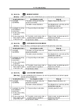
(22) Alarm No. 52 : EXCESSIVE ERROR
[Details]
The position tracking error during orientation exceeded the specified value (excessive
error width setting value).
•
Excessive error width setting value
During orientation (SP102: OODR): Standard value 32767 (32767 pulses)
During spindle synchronization (SP186: SODR): Standard value 32767 (32767 pulses)
During synchronous tap (SP218: TODR): Standard value 32767 (32767 pulses)
Investigation items
Investigation results
Remedy
The alarm occurs during orientation. Investigate item 2, and carry out the
appropriate measures.
The alarm occurs during spindle
synchronization.
Investigate item 7, and carry out the
appropriate measures.
1 Investigate
repeatability.
The alarm occurs during
synchronous tap.
Investigate item 11, and carry out the
appropriate measures.
The trouble is eliminated by
changing the bit5 setting value.
Change the bit5 setting value.
2 If the alarm occurs
during encoder
orientation, check the
spindle parameter
(SP097: SPEC0) bit5
setting value.
The trouble is not eliminated by
changing the bit5 setting value.
Return bit5 to the original setting
value. Investigate item 3, and carry
out the appropriate measures.
The trouble is eliminated by raising
the PGM and PGE values 2-fold, or
by halving the CSP value.
Change the setting value.
3 Check the spindle
parameter (SP001:
PGM, SP002: PGE,
P006: CSP) setting
values.
The trouble is not eliminated by
changing the values as shown
above.
Investigate item 4, and carry out the
appropriate measures.
Connector came (was coming) loose. Install correctly.
4 Jiggle the position and
speed detector
connectors (spindle
drive unit side and
position and speed
detector side) to see
whether they are
coming loose.
Connectors are normal.
Investigate item 5, and carry out the
appropriate measures.
The connection is faulty, or there is a
broken wire.
Replace the detector cable. Correctly
connect the cable.
5 Turn the power OFF,
and check the position
and speed detector
cable connection with
a tester.
The connection is normal.
Investigate item 6, and carry out the
appropriate measures.
The waveform is incorrect.
Adjust the waveform so it is correct.
Or, replace the detector.
6 Check the speed
detector waveform.
The waveform is correct.
Replace the unit or detector.
The trouble is eliminated by
changing the bit5 setting value.
Change the bit5 setting value.
7 If the alarm occurs
during spindle
synchronization, check
the spindle parameter
(SP177: SPECS) bit 5
setting value.
The trouble is not eliminated by
changing the bit5 setting value.
Return bit5 to the original setting
value. Investigate item 8, and carry
out the appropriate measures.


