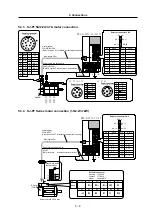
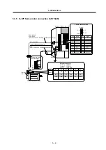
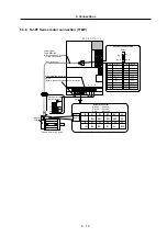


5. Connections
5
−
22
(2) Wire and assembly of detector cables and communication cables
The wire specifications and manufacturing methods for each cable are shown below. Use the
recommended wire or equivalent parts in the following table when manufacturing the cable, and
be sure to connect all parts correctly.
Core size
[mm
2
]
×
one pair
Outline of the core insulation
sheath (Note) d [mm]
Recommended
wire model
Cable type
0.08
×
10
UL20276
AWG28 10 pair
(Black)
Serial bus cable
(CN1A/CN1B)
0.3
×
12
0.9 ~ 1.27
UL1061-2464
AWG22 12 pair
(Black)
Standard detector
cable
Note
: d is as shown in the following drawing.
d
Insulation sheath
Conductor
Cross-section of the wire core
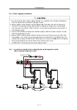
Securely connect the cable shield wire to the connector grounding plate as shown in the following
drawings.
Grounding plate
Sheath Conductor
Shield
(external conductor)
Wire core
Sheath Conductor
Shield
(external conductor)
Wire core


