


23
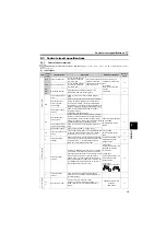
Control circuit specifications
2.3.3
Wiring of control circuit
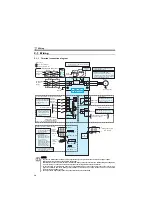
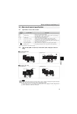
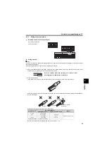
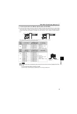
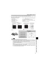
(1) Standard control circuit terminal layout
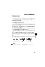
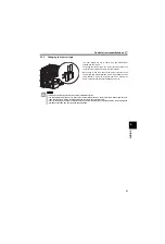
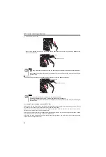
(2) Wiring method
Wiring
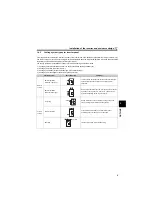
Use a bar terminal and a cable with a sheath stripped off for the control circuit wiring. For a single wire, strip off the sheath of
the cable and apply directly.
Insert the bar terminal or the single wire into a socket of the terminal.
1) Strip off the sheath about the size below. If the length of the sheath peeled is too long, a short circuit may occur among
neighboring wires. If the length is too short, wires might come off.
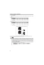
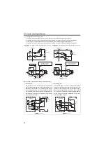
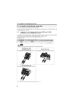
2) Crimp the bar terminal.
Insert wires to a bar terminal, and check that the wires come out for about 0 to 0.5 mm from a sleeve.
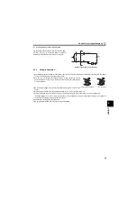
Check the condition of the bar terminal after crimping. Do not use a bar terminal of which the crimping is inappropriate, or
the face is damaged.
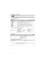
Introduced products on bar terminals :(as of Mar., 2008)
Bar terminal crimping tool: CRIMPFOX ZA3 (Phoenix Contact Co., Ltd.)
Recommend cable size:
0.3mm
2
to 0.75mm
2
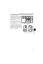
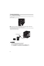
Wire the stripped cable after twisting it to prevent it from
becoming loose. In addition, do not solder it.
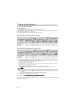
Wire Size (mm
2
)
Bar Terminal Model
Maker
With Insulation Sleeve
Without Insulation Sleeve
0.3, 0.5
AI 0,5-10WH
—
Phoenix Contact Co.,Ltd.
0.75
AI 0,75-10GY
A 0,75-10
1
AI 1-10RD
A1-10
1.25, 1.5
AI 1,5-10BK
A1,5-10
0.75 (for two cables)
AI-TWIN 2 x 0,75-10GY
—
STF STR
PC
SD
RH
RM
RL
AM
C
B
A
10
2
5
4
RUN SE
S1 S2 SC
SO
SD
Cable stripping size
10mm
Sleeve
Shell
Cable
Unstranded
wires
Damaged
Wires are not inserted
into the shell
Crumpled tip
Summary of Contents for FR-D700 Series
Page 11: ...VII MEMO ...
Page 23: ...12 MEMO ...
Page 57: ...46 MEMO ...
Page 262: ...258 MEMO ...
Page 276: ...272 MEMO ...
Page 287: ...283 MEMO ...
Page 289: ......