


278
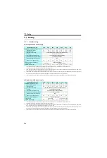
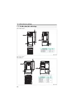
Outline dimension drawings
Parameter unit (option)
(FR-PU07)
<
Outline drawing>
<
Panel cut dimension drawing
>
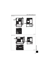
Parameter unit (option) (FR-PU04)
<
Outline drawing>
<
Panel cut dimension drawing>
Enclosure surface operation panel (option) (FR-PA07)
<
Outline drawing>
<
Panel cut dimension drawing>
67
51
40
56.8
57.8
26.5
4-R1
26.5
40
4-
φ
4 hole
(
Effective depth of the
installation screw hole 5.0)
M3 screw *2
Air-bleeding
hole
80.3
(14.2)
2.5
50
(11.45)
25.05
135
83
*1
*1
*1
*1
∗1
When installing the FR-PU07 on the enclosure, etc., remove screws or fix the screws to the FR-PU07 with M3 nuts.
∗2
Select the installation screw whose length will not exceed the effective depth of the installation screw hole.
(Unit: mm)
40
5-
φ
4 hole
23.75
11.75
81.5
1.25
1.5
13
17
16.5
1.5
125
72
15
10.5
18.5
40
80
48
5-M3 screw
24
13
20
21.5
14.5
Effective
depth
of the
installation
screw hole 4.5
Select the installation screws whose length will not exceed the effective depth of the installation screw hole.
(Unit: mm)
68
59
22
22
2-M3 screw
(Unit: mm)
Summary of Contents for FR-D700 Series
Page 11: ...VII MEMO ...
Page 23: ...12 MEMO ...
Page 57: ...46 MEMO ...
Page 262: ...258 MEMO ...
Page 276: ...272 MEMO ...
Page 287: ...283 MEMO ...
Page 289: ......