18
Kaleido-X16 Installation
Control
1
Control
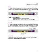
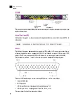
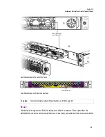
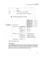
The connectors located in the middle of the rear connector panel (the yellow and orange color-coded area)
are
Control
connectors.
Linear Time Code (LTC)
The Kaleido-X16 supports two linear time code (LTC) inputs over BNC connectors. The format is SMPTE 12M
unbalanced.
GPI I/O
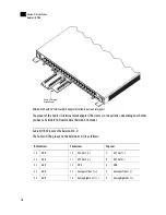
The Kaleido-X16 supports status monitoring, genlock and GPI interfacing. The rear connector panel houses
all input and output connectors associated with GPI I/O. The Kaleido-X16 supports 32 GPI inputs and 4 GPI
outputs. The GPI connector type is a DSUB-44 (female on the connector panel; male on the cable):
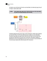
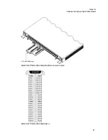
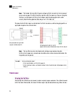
The pin numbering scheme for the GPI I/O connector is represented in the following diagram:
There are 44 GPI connector pins (40 not including GND) whose functions are as follows:
• 4 Ground (GND) pins
• 32 GPI Input pins
• 4 GPI Output Emitter pins (designated in the table, below, as “N”)
• 4 GPI Output Collector pins (designated in the table, below, as “P”)
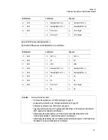
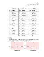
The exact pinout for the GPI connector is as follows:
See also:
For more information about LTC specifications, see “Time Code Inputs (LTC)” on page 68.
BNC connectors
for LTC inputs
USB connectors (2)
RJ-45 connectors (2)
for RS-422 serial
connections
RJ-45 Ethernet
connector
DSUB-44 connector
for GPI I/O
Pin 15
Pin 1
Pin 30
Pin 44
Pin 31
Pin 16
Summary of Contents for Kaleido-X16
Page 4: ......
Page 32: ...26 Kaleido X16 Installation Replacing a Defective Power Supply 1 ...
Page 80: ...74 Specifications Physical Dimensions 3 ...
Page 82: ......


