background image

2  |  minnkotamotors.com

©2020 Johnson Outdoors Marine Electronics, Inc.

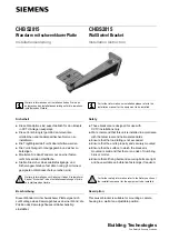
a.  Disconnect the Talon from power before beginning 

the installation. 

b.  Remove the Talon from the Mounting Bracket by 

loosening the four Nylock Nuts that hold the Talon in 

place. Do not remove the nuts, only loosen them. 

g.  Align the Setback Bracket with the mounting holes 

in the Transom. Depending on the holes that were 

originally used to mount the Talon Mounting Bracket, 

new holes may need to be drilled in the Setback 

Bracket.

h.  Place a 1/8” bead of Marine Grade Sealant (not 

included) on the Transom of the boat around the 

mounting holes where the hardware and Mounting 

Bracket were just removed.

i. 

Place the Marine Grade Sealant on the face of the 

Setback Bracket that will contact the boat Transom 

when mounted. Keep the sealant approximately 

centered between the outside edge of the Setback 

Bracket and the Mounting Holes. Once the sealant 

is in place, align the Setback Bracket in the desired 

orientation with the existing Mounting Holes that were 

drilled in the Transom.

Installation with Talon Already Installed

Transom

Transom

Mounting 

Mounting 

Bracket

Bracket

Mounting 

Mounting 

Bolt

Bolt

Flat Washer

Flat Washer

1

2

2g

Marine Grade Sealant

Marine Grade Sealant

Mounting Hole

Mounting Hole

Transom

Transom

1e

1b

1a

Talon

Talon

Talon 

Talon 

Mounting 

Mounting 

Bracket

Bracket

Talon

Talon

Power 

Power 

Cord

Cord

Nylock 

Nylock 

Nut

Nut

Inboard

Inboard

Outboard

Outboard

INSTALLATION

NOTICE:

 It may be necessary to have a second 

person hold the Talon while the Nylock Nuts are 

being loosened.

c.  Lift the Talon out of the Mounting Bracket and set 

it aside, making sure there is enough slack in the 

Power Cord to do so. If routed through the Transom, 

the Power Cord does not have to be pulled through 

the Transom to complete the installation.

d.  Using a 1/2” Box End or Socket Wrench, remove the 

four Nylock Nuts and Fender Washers on the inside of 

the Transom that hold the Mounting Bolts in place.

e.  Remove the four 5/16” x 3-1/2” Mounting Bolts that 

attach the Mounting Bracket to the Transom. These 

same Bolts will be used to attach the 6” Setback 

Bracket to the transom.

f. 

Retain the Nylock Nuts, Fender Washers, Flat 

Washers and Mounting Bolts to attach the 6” 

Setback Bracket to the Transom.

2h

Setback Bracket

 Bracket

Marine Grade Sealant

Marine Grade Sealant

Marine Grade Sealant

Marine Grade Sealant

Nylock 

Nylock 

Nut

Nut

Fender Washer

Fender Washer

Transom

Transom

Mounting 

Mounting 

Bracket

Bracket

1f

Summary of Contents for 1810220

Page 1: ...assembly and cannot be ordered individually The Talon Setback Bracket provides six inches of additional setback for direct transom mount applications This provides extra clearance for accessories such...

Page 2: ...Mounting Mounting Bolt Bolt Flat Washer Flat Washer 1 2 2g Marine Grade Sealant Marine Grade Sealant Mounting Hole Mounting Hole Transom Transom 1e 1b 1a Talon Talon Talon Talon Mounting Mounting Bra...

Page 3: ...s positioned tighten the mounting hardware with a 1 2 Box End or Socket Wrench 3 3f 3g Setback Setback Bracket Bracket Mounting Bolt Mounting Bolt Transom Transom Fender Washer Fender Washer Flat Flat...

Page 4: ...t Marine Grade Sealant e Install the Setback Bracket to the Transom using the mounting hardware that was provided with the Talon The Mounting Bolts should pass through the Flat Washers Setback Bracket...

Page 5: ...he approximate final position f Carefully lift the Talon Assembly into the Mounting Bracket and align the Mounting Straps with the Assembly Track Slide the Guard Washers to the inside wall of the Moun...

Page 6: ...top Bolt NOTICE For details on Talon mounting adjustments please refer to the Owner s Manual or Installation Instructions online at minnkotamotors com CAUTION Check tension of the 4 vertical adjustmen...

Page 7: ...e command e individuellement Le support de d calage du Talon procure un d calage suppl mentaire de six pouces pour un montage direct au tableau arri re Ceci procure davantage de d gagement pour les ac...

Page 8: ...alit marine qualit marine Trou de montage Trou de montage Tableau arri re Tableau arri re 1e 1b 1a Talon Talon Support de Support de montage montage Talon Talon Talon Talon Cordon Cordon d alimentatio...

Page 9: ...cliquet de 1 2 po 12 mm 3 3f 3g Support Support de de d calage d calage Boulon de Boulon de montage montage Tableau Tableau arri re arri re Rondelle de Rondelle de protection protection Rondelle Rond...

Page 10: ...ur le tableau arri re au moyen de la quincaillerie de montage livr e avec le Talon Les boulons de montage devraient passer travers les rondelles plates le support de d calage puis dans le tableau arri...

Page 11: ...du Talon dans le support de montage et aligner les sangles de montage avec la piste d assemblage Faire glisser les rondelles de s ret sur la paroi int rieure du support de montage a n qu elles soient...

Page 12: ...ements de montage du Talon consulter le manuel du propri taire ou les directives d installation en ligne sur minnkotamotors com ATTENTION V ri er la tension des quatre crous d ajustement vertical apr...

Reviews: