


AN-48-003 Rev. H (Jun 09, 2022) This document and its contents are the property of Mini-Circuits ECO-013719 Page 21 of 44
3.1.10
The Ethernet Configuration settings are:
# Name
Description
1
MAC Address
Media Access Control Address – a unique, unchanging identifier for the
smart power meter unit.
2
Network
Gateway
IP address of the network gateway. When DHCP is selected this is assigned
by the server.
3
Subnet Mask
The Network's Subnet Mask. When DHCP is selected this is assigned by the
server.
4
IP Address
The IP address of the unit in your Network. When DHCP is selected this is
assigned by the server.
5
Use DHCP
When selected the smart power meter will query the server for appropriate
parameters with no input from the user and will disregard manually entered
IP address, subnet mask and network gateway settings.
6
Refresh
Request IP address, gateway and subnet mask from the server.
7
Copy State
Copies current state of dynamic IP to static IP, not available when DHCP is
selected.
8
Static
Configuration
When DHCP is not selected the user must specify the values below and will
not be changed by the server.
9
Telnet Port
Port to be used for Telnet communication. Cannot be changed by user
10
Store
After you've made all the changes you want to click on this button to save the
settings.
11
Password
If you want to limit the users able to access the power sensor select "Use
Password" and enter the desired password (up to 20 characters).
12
HTTP Port
Specify the port to use for HTTP communication with the network (default
80). Note port address does not get assigned by the server when DHCP is
selected. Port 23 is reserved for Telnet communication and cannot be used.
3.1.11
After making the changes you want, click on "Store"
and the
changes will be saved to the smart power meter's memory. See
section 3.2
Ethernet control
.
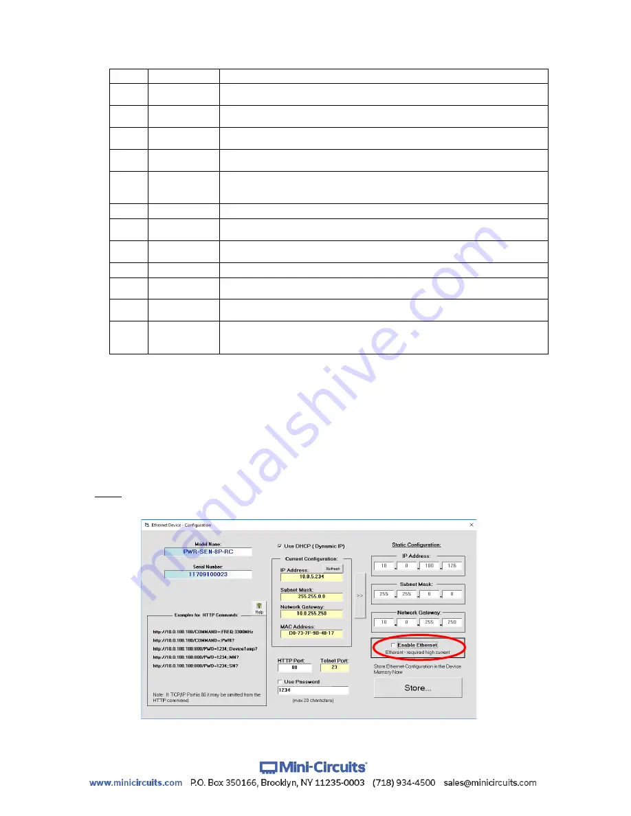
3.1.12
For Peak and Average power sensors
only, the Ethernet control circuitry
needs to be specifically enabled before power sensor can be used via Ethernet by selecting
the “Enable Ethernet” option and clicking “Store”. Once Ethernet control is enabled you can
proceed as described for other RC suffix models.
Note:
When Ethernet is enabled the power sensor may draw over 500mA. This may cause
issues if attempting to power it from a USB 2.0 port.
Figure 3.1.12:
Ethernet Config. screen for Peak power sensor


