


17
1)
Peak value (4 stations)
Area indicating the peak value
Data type:
Signed 32-bit binary
Data range:
-999999~999999
2)
Track value (4 stations)
Area indicating the track value
Data type:
Signed 32-bit binary
Data range:
-999999~999999
3)
Error code (4, 2, or 1 station)
Area indicating errors on the indicator
For error details, see "(4) Auxiliary error code".
Data type:
16-bit binary
Data range:
0~255
4)
Auxiliary error code (4, 2, or 1 station)
Area indicating error numbers on the indicator
Data type:
16-bit binary
Data range:
0~255
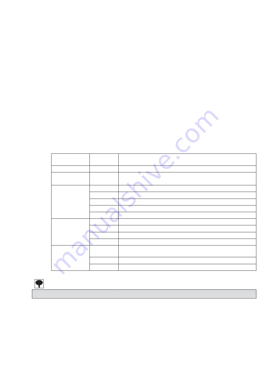
Error code
Auxiliary
error code
Details
0
0
No error
2
Zero set error
1
Zero set error
If zero set is executed under conditions when this is not possible
3
Other error
3
A/D conversion error
31
EEPROM write error
32
EEPROM readout error
51
DAC abnormality
99
Other than measurement mode
4
Calibration error
0
TE-L error
1
TE-H error
2
SP-L error
3
SP-H error
99
Setting error
0
Undefined command received
When irregular data is set in a command number
1
Out-of-range error
2
Unexecutable error
Also refer to error display information in the device instruction manual for error details.
Summary of Contents for CC-Link CSD-709-73
Page 1: ...DIGITAL PEAK HOLDER CC Link Interface CSD 709 73 Instruction Manual EN294 1701 ...
Page 2: ......
Page 8: ......