background image

4

Troubleshooting

If the tool does not turn on:

• Ensure  battery  is  installed  properly.  Fuel  gauge 

should indicate remaining charge when correctly 

installed.

• Ensure battery is charged.

• Ensure the tool's internal temperature is within speci-

fied operating ranges. If stored in excessive heat or 

cold, allow at least 2 hours to acclimate to ambient 

temperature before turning on the tool.

If problem persists, please contact a MILWAUKEE 

service facility for support.

ACCURACY FIELD CHECK

NOTICE

Perform the Accuracy Field Check 

procedure immediately upon unboxing 

of each new Laser Level and before exposure to 

jobsite conditions. See "Accuracy Field Check" 

for information. 

Should any deviation from listed 

product accuracy be found, please con-

tact a MILWAUKEE service facility. Failure to do so 

could result in rejection of warranty claim.

Influences on Accuracy

Ambient temperature gradients can impact laser 

accuracy. For accurate and repeatable results, the 

following procedure should be conducted with the 

laser elevated off the ground and placed in the center 

of the working area.

Abusive treatment of the Laser Level, such as exces-

sive impacts from drop, can also lead to deviations 

in product accuracy.

Therefore, it is recommended to conduct the Field 

Check procedure after any impact or before complet-

ing any critical jobs.

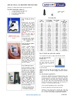
Horizontal Height Accuracy

A free measuring distance of approximately 66' on a 

firm surface between two walls or structures A and 

B is required for this check.

It is also suggested to mount the Laser Level to a 

Tripod for easy adjustment. 

1. Securely mount the tool within 1' of wall A. 


A

B


1'

66'

2. 

Turn the tool to 

 ON and to Perpendicular Level, 

Plumb Points, & Horizontal Points mode.

3. 

Direct the front laser beam against the nearest 

wall A and allow to self-level. Mark the center of 

the laser cross on the wall (point I).

4. 

Rotate the tool 180° without changing the height, 

allow it to self-level, and mark the center of the 

laser cross on the opposite wall B (point II).

OPERATION

WARNING

To reduce the risk of injury or tem-

porary  effects  on  vision,  do  not 

look directly into the laser when it is on.

CAUTION

Use of controls or adjustments or 

performance of procedures other 

than those specified herein may result in hazard

-

ous radiation exposure.

NOTICE

Perform the Accuracy Field Check 

procedure immediately upon unboxing 

of each new Laser Level and before exposure to 

jobsite conditions. See "Accuracy Field Check" 

for information.

Turning On/Off

To turn on the laser and unlock the pendulum, rotate 

the On/Off dial to the desired position. The remaining 

battery life will be displayed. 

WARNING!

 Do not look 

directly into laser apertures. Horizontal level line and 

left/right  plumb  points  will  immediately  be  emitted 

from aperture in the laser housing.

 ON 

Turns ON the laser and unlocks the pendu

-

lum to enable self-leveling.


ON 

Turns ON the laser but does not unlock the 

pendulum  (self  leveling  is  disabled). The 

laser lines will flash once every 8 seconds 

to indicate that the projected lines and dots 

are not level or plumb.


NOTICE:

 The 

 ON mode disables self-

leveling and therefore is not intended for 

projecting a level or plumb lines/points.   


OFF

   Turns  OFF  the  laser  and  locks  the  pen

-

dulum. When not in use, turn off the tool 

and store the Laser Level in the protective 

carrying case

Use  the  MODE  button  to  cycle  through  the  three 

laser modes: 

•Horizontal Level Line & Horizontal Points

•Vertical Plumb Line & Plumb Points

• Perpendicular Level, Plumb Points and Horizontal 

Points

Using the Laser Level

1. 

For best results, place the tool on a work surface 

that is:

• sturdy

• level (within 4 degrees of true level)

• free of vibrations

• 90° to the work area

2. Turn on the tool.

3. 

The tool will self-level when placed on surfaces 

within 4 degrees of true level when dial is unlocked 

and on.

4. 

The tool is ready once the emitted lines are con-

tinuous and no longer moving on the work surface.

5. If the tool cannot achieve a level state (i.e., the 

work surface is > 4 degrees off true level), the laser 

beams will flash rapidly (3 flashes per second). 

Relocate or adjust the work surface.

Summary of Contents for 3624-20

Page 1: ...rator s manual AVERTISSEMENT Afin de r duire le risque de blessures l utilisateur doit lire et bien comprendre le manuel ADVERTENCIAPara reducir el riesgo de lesiones el usuario debe leer y entender e...

Page 2: ...lowallcharginginstructionsanddonotcharge the battery pack or tool outside the temperature range specified in the instructions Charging im properlyorattemperaturesoutsidethespecifiedrange may damage th...

Page 3: ...body of the tool Make sure it latches securely into place WARNING Only use accessories specifically recommended for this tool Others may be hazardous Power Save Use power save mode to extend the batt...

Page 4: ...f the laser cross on the opposite wall B point II OPERATION WARNING To reduce the risk of injury or tem porary effects on vision do not look directly into the laser when it is on CAUTION Use of contro...

Page 5: ...on a firm surface between two walls or structures A and B is required for the check It is also suggested to mount the Laser Level to a Tripod for easy adjustment Securely mount the tool on one side o...

Page 6: ...pening should not exceed 0 05 in a 7 doorway Plumb Dot Accuracy A free measuring distance of approximately 16 5 between floor and ceiling on a firm surface is required for this check 1 Place the tool...

Page 7: ...aning Clean dust and debris from any vents Keep tool clean dry and free of oil or grease Use only mild soap and a damp cloth to clean since certain clean ing agents and solvents are harmful to plastic...

Page 8: ...IN ANY PRODUCT INCLUDING BUT NOT LIMITED TO ANY CLAIMS FOR LOSS OF PROFITS SOME STATES DO NOTALLOW THE EX CLUSION OR LIMITATION OF INCIDENTAL OR CONSEQUENTIAL DAMAGES SO THEABOVE LIMITATION OR EXCLUSI...

Page 9: ...ez que le travail d passe votre capacit veuillez contacter MilwaukeeTool ou un professionnel form pour recevoir plus d information ou formation Maintenir en tat les tiquettes et les plaques signal tiq...

Page 10: ...omporter des risques conomie d nergie Utilisez le mode d conomie d nergie pour prolon ger l autonomie de la batterie Le mode d conomie d nergie est indiqu par des faisceaux laser att nu s et le cligno...

Page 11: ...les lignes mises sont continues et ne se bougent plus sur la sur face de travail 5 Si l outil n arrive pas achever un tat de nivel lement c est dire la surface de travail est 4 degr s hors du niveau r...

Page 12: ...sur le mur A repr sente la d viation d de hauteur de l outil Cette distance ne devra pas d passer 3 mm 1 8 max 91 cm 3 13 mm 1 2 40 m 132 Par rapport la distance de mesure de 2 x 20 m 66 x 40 m 132 l...

Page 13: ...soit directement align sur les points I et II 6 Marquer le centre de la ligne verticale sur le rebord sup rieur de l ouverture de la porte point IV 7 Mesurer la hauteur de l ouverture de la porte 8 L...

Page 14: ...point I au croisement des lignes directement en face du laser projet sur le mur A Sans bouger le laser marquer aussi le centre du point Horizontal droit II sur le mur B 10 m 33 10 m 33 10 m 33 A B C 2...

Page 15: ...ces produits La p riode de garantie couvrant les radios de chantier le port d alimentation M12 la source d alimentation M18 le ventilateur de chantier et les chariots de chantier industriels Trade Ti...

Page 16: ...clavos tornillos u otros objetos met licos peque os que puedan formar una conexi n de una terminal a otra Crear un corto entre las terminales de la bater a puede ocasionar quemaduras o un incendio Ba...

Page 17: ...una o m s de las siguientes medidas Reorientar o reubicar la antena receptora Aumentar la distancia entre el equipo y el receptor Consulte al distribuidor o a un t cnico experimentado de radio TV para...

Page 18: ...e microajuste para afinar las l neas verticales OPERACION ADVERTENCIA Para reducir el riesgo de le siones o efectos temporales en la vista no mire directamente hacia el l ser cuando est encendido ATEN...

Page 19: ...e recomienda realizar un procedimiento de revisi n del campo despu s de cualquier impacto o antes de completar cualquier trabajo esencial Precisi n de la altura horizontal Se necesita una distancia de...

Page 20: ...l punto II de la pared 4 Marque el punto central del rayo l ser en la pared A punto III 5 La distancia d entre los puntos I y III marcados en la pared A indica la desviaci n real d de la herramienta A...

Page 21: ...ntro del punto de plomada en el piso punto II 5 m 16 5 4 Gire la herramienta 180 Alinee el punto central del rayo l ser directamente en el punto II del piso 5 Marque el centro del punto de plomada sup...

Page 22: ...le siones personales y da os materiales nunca sumerja su herramienta en l quido ni permita que un l quido fluya hacia su interior Limpieza Limpie el polvo y suciedad de las cualquier ventilas Mantenga...

Page 23: ...el ctrica de MILWAUKEE La fecha de fabricaci n del producto servir para deter minar la vigencia de la garant a si no se presenta ning n comprobante de compra al solicitar el servicio en garant a LA AC...

Page 24: ...58143624d2 01699300101Q 02 A 04 22 Printed in China MILWAUKEE TOOL 13135 West Lisbon Road Brookfield WI 53005 USA...

Reviews: