Air Driven Gas Booster Compressor, 8” Drive AG Series • OM-12J
3
seals, retainers and bearings, all enclosed by an end cap incorporating inlet and outlet check valve
assemblies.
NOTE: The seals on the connecting rods are also considered part of the gas sections. Each rod has a
dual seal design with a small vent between to dissipate minor air drive leakage. The chambers on the
inside of the gas barrels, behind the gas pistons, are piped to a tee with a filtered breather (on standard
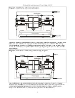
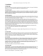
models). See Figures 1 & 2.
No lubrication of any kind is ever used on the dynamic seals of the gas pumping sections.
They
are designed to run dry, supported on the inherent low friction properties of the seal and bearing
materials.
The life of the gas pumping section depends on the cleanliness of the gas supply. Therefore, micronic
filtration is suggested at the gas inlet port. If compressed air or other moisture containing gas is to be
pumped, the initial dew point should be low enough to prevent saturation at booster output pressure, and
if any carry over of oil from a compressed air source is evident, special coalescing type filtration may be
necessary.
Over the life of the moving parts, some migration of inert particles into the gas output should be expected.
Therefore, a small particle filter on the high pressure output line may be advisable for critical applications.
2.3.1 COMPRESSION RATIO - VOLUMETRIC EFFICIENCY
(Not to be confused with "Area Ratio")
The compression ratio of any gas section is the ratio of output gas pressure to inlet gas pressure. (To
calculate, use PSI absolute values.) The gas pumping sections are designed to have minimum unswept
or clearance volume at the end of the compression stroke. On the return (suction) stroke of the piston,
output pressure in the unswept volume re-expands. This reduces the amount of potential fresh gas intake
on the suction stroke. Volumetric efficiency therefore decreases rapidly with an increase in compression
ratio. The volumetric efficiency reaches zero when the unexpelled (re-expanded) gas completely fills the
cylinder and equals the supply gas pressure at the end of the intake stroke. For example: A cylinder with
a 4% unswept volume will reach zero efficiency at a compression ratio of approximately 25:1 because the
inlet check valve will no longer open at any point during the suction stroke to admit fresh gas. Therefore,
applications requiring high compression ratios are preferably handled by the 2 stage (BAGT) models or 2
or more 8AGD models piped in series.
Production models of Haskel gas boosters are tested in the laboratory. Results of these tests indicate that
compression ratios of up to 40:1 are possible for some individual stages under ideal conditions. However,
for satisfactory operation under production conditions in industrial applications, we recommend
compression ratios (per stage) of about 10:1 or less. Operation at higher ratios per stage may not
damage the gas booster, but because output flow and efficiency will be low, the use should be limited to
pressurizing small volumes such as pressure gauge testing, etc.
2.3.2 COOLING AND EXHAUST SYSTEM
In theory, compression ratios above 3:1 with most gases produce temperatures above the allowable limits
for the seals. In practice, however, the heat of compression is transferred to the air cooled gas barrel and
adjacent metal components during the relatively slow speed of the piston on the compression stroke and
these components will stay within allowable temperature limits. Laboratory tests indicate that maximum
temperatures occur between compression ratios of 5:1 and 10:1 and have shown that exhaust air cooling
is adequate even when the booster is running at full speed. The allowable gas discharge temperature
may run as high as 150°F above ambient temperature.
Effective cooling of the gas pumping section(s) is important as service life of piston seals, bearings, and
static seals are dependent upon proper operating temperatures. Driving air expands during the exhaust
stroke with a significant reduction in temperature. Therefore, this chilled exhaust air routed through the
cooling barrels surrounding the gas barrels and shell of the plenum cooler surrounding the output and
interstage gas lines is a very efficient cooling medium.
In both the 8AGD and 8AGT series boosters the cold air drive exhaust enters the plenum cooler and is
then routed to each gas barrel cooling jacket. In the 8AGD series single stage, double acting models, the
hot high pressure output gas from both of the gas section pumps is aftercooled by passing through the
plenum cooler prior to final output. (Figure 1.)
Summary of Contents for Haskel 8AGD-1
Page 15: ...8 OM 12J 15 2 3 T 2 3 1 4 25 1 8AGT 8AGD 40 1 10 1 2 3 2 3 1 5 1 10 1 80 C...
Page 16: ...8 OM 12J 16 1 8AGD 8AGT 2 8AGT 25mm 145 C...
Page 18: ...8 OM 12J 18 3 5 1 2 2 3 4 4 1 1 bar 5 5 1 CV No 242 CV O...
Page 19: ...8 OM 12J 19 IPA 50 50 5 2 5 2 1 5 2 2 3 O O 4 5 2 3 5 3 4 5...
Page 24: ...8 OM 12J 24 O 5 7 8 5 7 9 6 6 1 6 2 70 bar 6 3...
Page 26: ...8 OM 12J 26 7 7 1 7 2 7 3 1 4 bar 5 2 O O O 9 5 5 5...
Page 29: ...8 AG OM 12J 29 8AGD 8AGT 8AGD 1 2 1 1 8AGD 8AGT 2 2 1 2 2 2 8AGT...
Page 31: ...8 AG OM 12J 31 3 5 1 2 2 3 4 4 1 15 psi 5 5 1 Loctite CV Blue 242 Loctite CV O...
Page 32: ...8 AG OM 12J 32 Stoddard 50 50 5 2 5 2 1 4 5 2 2 3 O O 4 3 4 Pilot shaft end seal...
Page 38: ...8 AG OM 12J 38 B 80 500 psi 7 7 1 7 2 7 3 20 psi 5 2 O O 9 5 5 6 O 6...
Page 41: ...8 AG OM 12J 41 1 8AGD 8AGT 2 2 8AGT 1 300 F...
Page 43: ...8 AG OM 12J 43 4 1 15 PSI 5 5 1 Loctite CV 242 Loctite CV O 50 50 5 2 5 2 1...
Page 44: ...8 AG OM 12J 44 5 2 2 3 O O 4 5 2 3 5 5 2 3 1 O 2 2 1 6 30 5 2 4 5 2 1 5 2 3 3 4 5 6...
Page 48: ...8 AG OM 12J 48 5 7 3 O 5 7 4 O O 5 7 5 O 5 7 6 5 1 5 7 7 O 5 7 8 5 7 9 6 6 1 6 2 1000 PSlG 6 3...
Page 50: ...8 AG OM 12J 50 7 7 1 7 2 7 3 20 psi 5 2 O O 9 5 5 5 O 6...


