Air Driven Gas Booster Compressor, 8” Drive AG Series • OM-12J
11
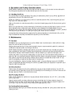
5.7.3
Remove end cap and/or retaining plate. Inspect O-ring and back up ring mounted inside end cap
and replace if damaged, worn or swollen.
5.7.4
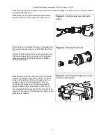
Remove cooling sleeve (with attached muffler), high pressure gas barrel and static seal O-rings.
Inspect O-rings and replace if damaged, worn or swollen.
5.7.5
The remainder of disassembly depends upon the parts make up shown on your particular assembly
drawing. The extent of disassembly should be determined by the initial reasons for disassembly; that is
end cap seal leakage, gas piston seal leakage, or air drive rod seal leakage. O-rings, seals and backup
rings are the most likely parts requiring replacement and are coded for kit replacement.
5.7.6
Clean all parts (Ref. Paragraph 5.1) and inspect for nicked, grooved, scratched or scored wear
surfaces and believille spring deformation.
5.7.7
Replace all parts that are damaged. Inspect high pressure gas barrel bore with a strong light. It
must be “mirror smooth”. However, if only slightly scratched it may be salvaged with a light hone.
NOTE: DO NOT apply a lubricant of any kind to bearings, seals, O-rings, backup rings or inner surface of
gas barrel.
5.7.8
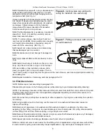
Reassemble gas piston parts in reverse order of disassembly. Final tightening and cotter pinning of
gas piston nut must be done with parts inside gas barrel. Refer to assembly instructions on assembly
drawing for final details.
5.7.9
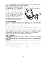
Alternately (crosswise) torque tie rods nuts to maximum torque value per assembly drawing notes.
6. Compression Test
– Gas Section and Check Valves
6.1 Purpose
Quick evaluation of the integrity of any individual pump section (before or after repair).
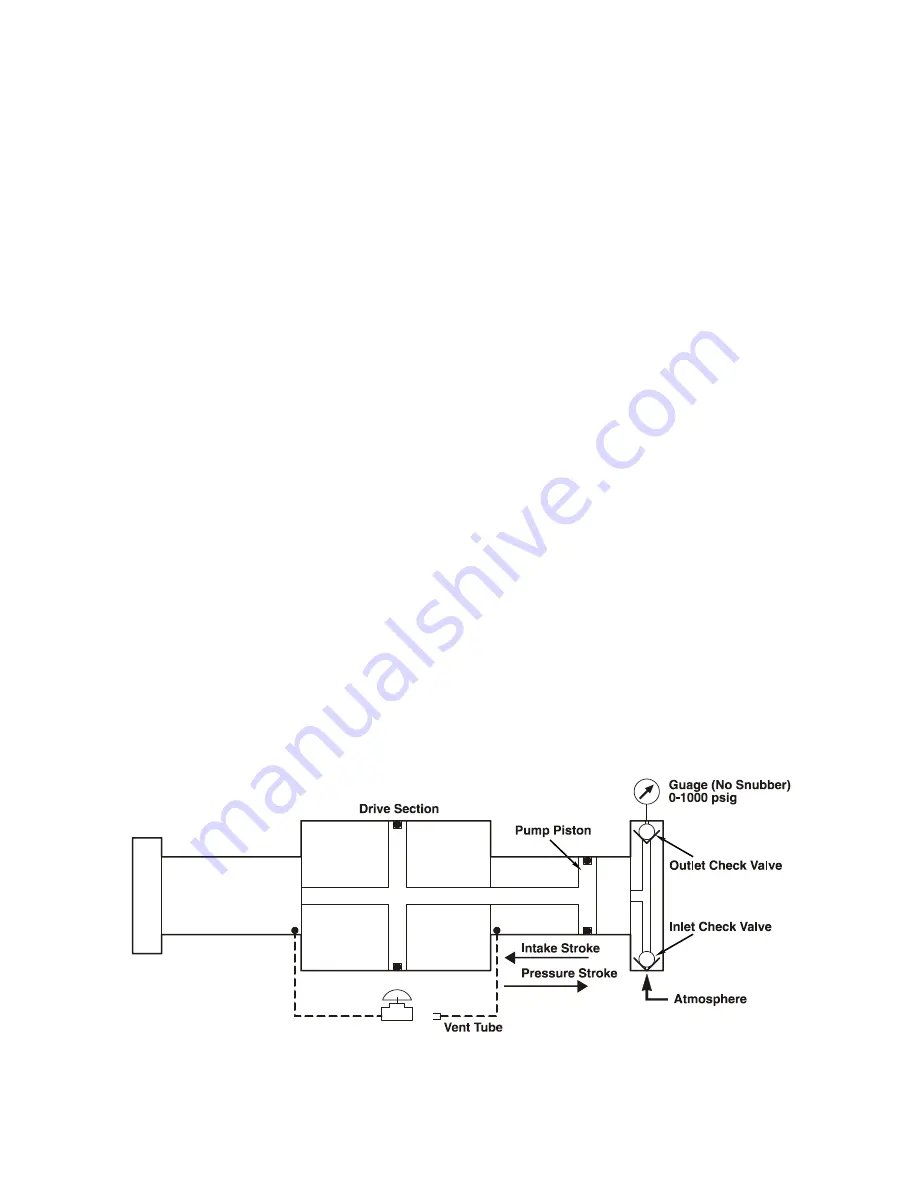
6.2 Theory - Drive Section
Each gas booster pump end consists of a sealed piston reciprocating in a smooth bore gas barrel;
inhaling gas on the backstroke through the inlet check; expelling most of this gas on the forward stroke
through the outlet check.
Therefore:
THE CONDITION OF ALL THESE PARTS CAN BE MEASURED BY COMPRESSING AIR
DIRECTLY FROM ATMOSPHERE INTO A 1000 PSlG GAUGE ON ANY PUMP SECTION OF ANY
MODEL.
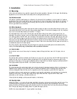
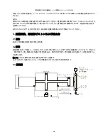
6.3 Schematic
Summary of Contents for Haskel 8AGD-1
Page 15: ...8 OM 12J 15 2 3 T 2 3 1 4 25 1 8AGT 8AGD 40 1 10 1 2 3 2 3 1 5 1 10 1 80 C...
Page 16: ...8 OM 12J 16 1 8AGD 8AGT 2 8AGT 25mm 145 C...
Page 18: ...8 OM 12J 18 3 5 1 2 2 3 4 4 1 1 bar 5 5 1 CV No 242 CV O...
Page 19: ...8 OM 12J 19 IPA 50 50 5 2 5 2 1 5 2 2 3 O O 4 5 2 3 5 3 4 5...
Page 24: ...8 OM 12J 24 O 5 7 8 5 7 9 6 6 1 6 2 70 bar 6 3...
Page 26: ...8 OM 12J 26 7 7 1 7 2 7 3 1 4 bar 5 2 O O O 9 5 5 5...
Page 29: ...8 AG OM 12J 29 8AGD 8AGT 8AGD 1 2 1 1 8AGD 8AGT 2 2 1 2 2 2 8AGT...
Page 31: ...8 AG OM 12J 31 3 5 1 2 2 3 4 4 1 15 psi 5 5 1 Loctite CV Blue 242 Loctite CV O...
Page 32: ...8 AG OM 12J 32 Stoddard 50 50 5 2 5 2 1 4 5 2 2 3 O O 4 3 4 Pilot shaft end seal...
Page 38: ...8 AG OM 12J 38 B 80 500 psi 7 7 1 7 2 7 3 20 psi 5 2 O O 9 5 5 6 O 6...
Page 41: ...8 AG OM 12J 41 1 8AGD 8AGT 2 2 8AGT 1 300 F...
Page 43: ...8 AG OM 12J 43 4 1 15 PSI 5 5 1 Loctite CV 242 Loctite CV O 50 50 5 2 5 2 1...
Page 44: ...8 AG OM 12J 44 5 2 2 3 O O 4 5 2 3 5 5 2 3 1 O 2 2 1 6 30 5 2 4 5 2 1 5 2 3 3 4 5 6...
Page 48: ...8 AG OM 12J 48 5 7 3 O 5 7 4 O O 5 7 5 O 5 7 6 5 1 5 7 7 O 5 7 8 5 7 9 6 6 1 6 2 1000 PSlG 6 3...
Page 50: ...8 AG OM 12J 50 7 7 1 7 2 7 3 20 psi 5 2 O O 9 5 5 5 O 6...


