Air Driven Gas Booster Compressor, 8” Drive AG Series • OM-12J
10
5.5.5
Inspect barrel to end cap static seal o-rings.
Pull barrel off drive piston and inspect large drive
piston seal.
NOTE: If the large o-
ring is “tight” in the groove, it is
probably swollen and should be replaced.
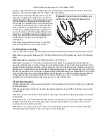
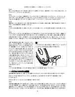
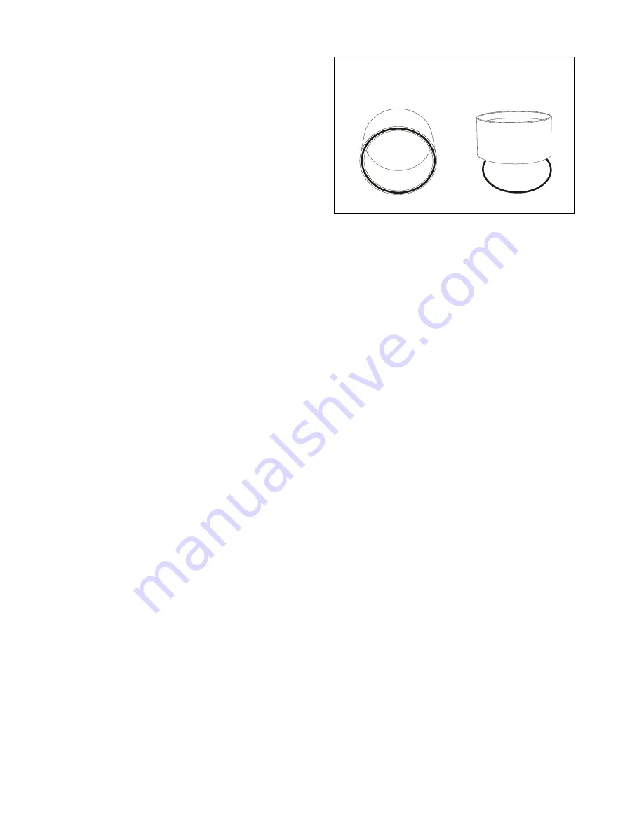
Replace if damaged or worn. Also, check large drive
piston o-ring for shrinkage by laying it on a flat
surface. Then place a clean unlubricated air barrel
over it. The o-ring outside diameter must be large
enough so that it can be picked up with the barrel. If
not, discard and replace. (Ref. Fig. 9.)
5.5.6
Clean all parts and inspect for grooved,
scratched or scored wear surfaces.
5.5.7
Apply Haskel 50866 Lubricant to all o-rings and inner surface of barrel and reassemble drive section
parts, end caps with pump sections, gas and associated plumbing lines in reverse order of disassembly
instructions.
5.5.8
Alternately (crosswise) torque tie rod nuts to 250 to 300 in-lbs.
5.6 Gas Check Valves
NOTE: The most obvious symptom indicating check valve repair is needed is that the gas end cap does
not heat up during operation. This means that little or no compression is occurring. (See also Paragraph
6. COMPRESSION TEST).
The parts makeup of the 8AGD series inlet and outlet check valves are the SAME for both gas piston end
caps; whereas the 8AGT series inlet and outlet check valves may be DIFFERENT for opposite gas piston
end caps. While the parts may be Identical for a particular series pump, it is important to note the
variations of position that relate to the location of these parts relative to the assembly of the
interconnecting gas piping and to refer to your detailed assembly drawing during repair.
5.6.1
Disconnect all plumbing lines necessary to allow access to the check valves.
5.6.2
Using suitable wrench, unscrew port fitting from end cap. Inspect O-ring on fitting and replace if
damaged, worn or swollen.
5.6.3
Remove remainder of parts inside check valve and inspect for damage or wear. Seats and O-rings
are most likely parts requiring replacement and are coded on the assembly drawing for kit replacement.
5.6.4
Clean all parts (Ref. paragraph 5.1) and inspect for nicks, grooves and deformation and renew any
that are damaged.
5.6.5
DO NOT apply lubricant to any of these parts.
NOTE: To properly center the parts during reassembly, we recommend that the ports be in a vertical
position. This may require the removal of the end cap in some instances.
5.6.6
Reassemble check valve parts in order shown on assembly drawing detail. Refer to assembly
drawing for special notes including torque required for tie rod nuts.
5.7 Gas Pistons
NOTE: Minute leakage of inlet gas past a high dynamic pressure gas piston seal is normal and can
usually be felt at the cross connected 21703-2 breather cap port with finger pressure (drive not cycling).
Audible leakage however indicates excessive gas piston seal wear. Disassemble gas pistons while
referring to your detailed assembly drawing in the following manner:
5.7.1
Disconnect all plumbing lines necessary to allow removal of gas section end caps.
5.7.2
Remove (4) nuts and lock washers from gas pump section tie rods.
NOTE: At this point, it is recommended that the entire gas section be pulled off as a unit from the drive
section by releasing the piston rod from the drive piston per Paragraphs 5.5.3 and 5.5.4. Then clamp the
gas end cap (or retaining plate) in a vise and proceed with further disassembly and reassembly.
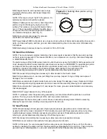
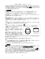
Figure 9.
Checking drive piston o-ring
for shrinkage
Summary of Contents for Haskel 8AGD-1
Page 15: ...8 OM 12J 15 2 3 T 2 3 1 4 25 1 8AGT 8AGD 40 1 10 1 2 3 2 3 1 5 1 10 1 80 C...
Page 16: ...8 OM 12J 16 1 8AGD 8AGT 2 8AGT 25mm 145 C...
Page 18: ...8 OM 12J 18 3 5 1 2 2 3 4 4 1 1 bar 5 5 1 CV No 242 CV O...
Page 19: ...8 OM 12J 19 IPA 50 50 5 2 5 2 1 5 2 2 3 O O 4 5 2 3 5 3 4 5...
Page 24: ...8 OM 12J 24 O 5 7 8 5 7 9 6 6 1 6 2 70 bar 6 3...
Page 26: ...8 OM 12J 26 7 7 1 7 2 7 3 1 4 bar 5 2 O O O 9 5 5 5...
Page 29: ...8 AG OM 12J 29 8AGD 8AGT 8AGD 1 2 1 1 8AGD 8AGT 2 2 1 2 2 2 8AGT...
Page 31: ...8 AG OM 12J 31 3 5 1 2 2 3 4 4 1 15 psi 5 5 1 Loctite CV Blue 242 Loctite CV O...
Page 32: ...8 AG OM 12J 32 Stoddard 50 50 5 2 5 2 1 4 5 2 2 3 O O 4 3 4 Pilot shaft end seal...
Page 38: ...8 AG OM 12J 38 B 80 500 psi 7 7 1 7 2 7 3 20 psi 5 2 O O 9 5 5 6 O 6...
Page 41: ...8 AG OM 12J 41 1 8AGD 8AGT 2 2 8AGT 1 300 F...
Page 43: ...8 AG OM 12J 43 4 1 15 PSI 5 5 1 Loctite CV 242 Loctite CV O 50 50 5 2 5 2 1...
Page 44: ...8 AG OM 12J 44 5 2 2 3 O O 4 5 2 3 5 5 2 3 1 O 2 2 1 6 30 5 2 4 5 2 1 5 2 3 3 4 5 6...
Page 48: ...8 AG OM 12J 48 5 7 3 O 5 7 4 O O 5 7 5 O 5 7 6 5 1 5 7 7 O 5 7 8 5 7 9 6 6 1 6 2 1000 PSlG 6 3...
Page 50: ...8 AG OM 12J 50 7 7 1 7 2 7 3 20 psi 5 2 O O 9 5 5 5 O 6...


