,
All electrical work must be car-
ried out by a suitably qualified and
competent person in accordance
with local and national safety regula-
tions.
^
Connection should be made via a
suitable isolator, with an on-off switch
which should be easily accessible for
servicing work.
^
For extra safety it is advisable to in-
stall a residual current device with a
trip current of 30 mA (in accordance
with DIN VDE 0664).
WARNING
THIS APPLIANCE MUST BE
EARTHED
^
Equipotential bonding should be car-
ried out.
Bonding connection
There is a screw connection point
marked with the earth symbol (
8
) at
the back of the machine, to which the
earth lead must be connected.
^
For technical data see data plate or
wiring diagram supplied.
The machine must only be operated
with the voltage, frequency and fusing
shown on the data plate.
This machine
can be converted
in ac-
cordance with the conversion diagram
and wiring diagram supplied.
The conversion diagram and data plate
with test certification (VDE, DVGW etc.)
is located on the rear of the machine,
and on the plinth (behind the service
panel).
The wiring diagram is secured to the
inner side of the service panel.
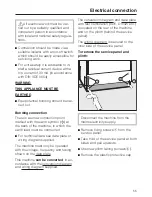
To remove the service panel and
plinth:
Disconnect the machine from the
mains electricity supply.
^
Remove fixing screws
a
from the
service panel.
^
Take hold of the service panel at both
sides and pull upwards.
^
Unscrew plinth facing (screws
b
).
^
Remove the plastic protective cap.
Electrical connection
55
Summary of Contents for G 7882
Page 3: ...Installation 53 Electrical connection 55 Plumbing 57 Technical data 60 Contents 3 ...
Page 65: ...61 ...
Page 66: ...62 ...
Page 67: ...63 ...

