inserted
. Once the two pieces are aligned, slowly lift the tool off of the drive ring plate.
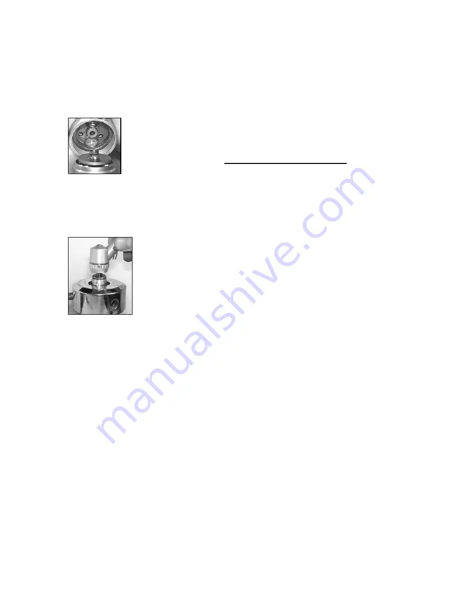
Use a small flat screwdriver to press the three drive rings into the clutch (as shown
above). This will correctly insert the wide drive rings and plate into the clutch housing.
This tool does not insert the drive ring into a 2-Speed the way it does on a 1-Speed. The
tool will align them, then, using a finger, keep them in place and use the screw driver to
slip each one down separately.
STEP 26
You now have two properly assembled Shorty halves. Sub Assembly A
and Sub Assembly B. Place any spacing washers that may have been
present back onto the outer edge of the clutch housing.
Now mesh the
two drive plate bearings into the two narrow drive rings in the motor
housing
. Once these are correctly aligned, begin to thread the two halves
together. Be sure not too cross-thread the pieces. If the pieces seem to stop threading
together right before they look properly seated, STOP. You may not have the drive plate
bearings aligned exactly inside the narrow drive rings. Back the pieces a part 1/16
th
of a
turn and retighten. If they still don’t align, unscrew the pieces and start this step over.
Forcing assembly A and B will break the LocTite loose on the turbine assembly.
STEP 27
To firmly tighten the two assemblies together, once again, place the
sheath housing into the ¾” collet. Insert the spindle into the housing.
Wrap the motor housing with a strip of rubber and tighten firmly in a
clockwise motion.