Sub Assembly B Reassembly (Motor Section)
STEP 13
Place the turbine raceway upside down on you work surface. Insert
the front turbine bearing into the appropriate hole (as shown). With
the bearing partially inserted, place a small dab of Loctite on the tip
of a needle and apply sparingly under the flange of the bearing.
Press the bearing firmly into the drive ring raceway and let sit.
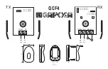
STEP 14
After the Loctite has cured, center the raceway, bearing side down, over
Hole# 7 in your work block (picture at left). Place the turbine spindle over
the hole in the bearing with the fat side up. Put your Lares assembly punch
in the top of the spindle and press the spindle into the bearing.
STEP 15
Now center the impeller over Hole# 6 in your work block. Place the small
end of the turbine spindle into the impeller (as shown). Using the same
Lares punch, press the spindle into the impeller.
STEP 16
If you did not replace the rear o-ring in
STEP 10
, do so now. Then reinstall the vent
plug.
STEP 17
Place the rear turbine bearing (40405C) into Hole # 2 of your work block.
Be sure the balls in the bearing are face down. Put the small end of the
turbine spindle into the bearing. Use the Lares punch to press the partial
turbine assembly into the bearing.
STEP 18
Insert the raceway tool into the three holes in the raceway. Carefully begin to thread the
raceway into the motor housing. A good tip is to turn the raceway counterclockwise until
a click is heard. Then begin to thread the pieces together. Once started, thread the
raceway securely into the housing until it bottoms out.
STEP 19
Now insert the two narrow drive rings into the drive
ring raceway 180 degrees apart. Notice there is a
small cut out portion on the inside edge of the drive
ring raceway. This allows you to insert the narrow
drive rings into the proper position.