


Servicing
5-3
board sockets. Carefully pry up the battery retaining lever. Then grasp the battery edges and remove
the device. Set the battery aside.
Note the “+” marking on one side of the replacement battery. When you install a battery, this “+”
marking must face the battery retaining lever. After replacing the battery, set the system clock to the
correct date and time. Also enter the Menu System and check or update system adjustments as
necessary.
•
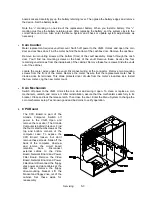
Coin Counter
Meter replacement requires vault removal. Switch off power to the VGM. Unlock and open the coin
door and cashbox door. Find the meter behind the bottom of the cashbox door. Remove the cashbox.
Remove two mounting screws at the bottom (front) of the vault assembly. Reach through the cash
door. You’ll find two mounting screws at the back of the vault. Remove these. Access the four
remaining vault screws from the inside-back of the cabinet. Remove these four screws. Slide the vault
out of the cabinet.
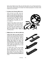
Locate the meter wires under the vault. Disconnect wiring at the connector. Remove two mounting
screws from the front of the meter. Remove the meter. Assure that the replacement meter has a
diode across its terminals. This diode protects driver circuits from the meter’s inductive kick. Install
the new meter. Log the new meter count.
•
Coin Mechanism
Switch off power to the VGM. Unlock the coin door and swing it open. To clean or replace a coin
mechanism, unlatch and remove it. After reinstallation, assure that the mechanism seats fully in its
bracket. Close and lock the release latch. Then close the door. Enter the Menu System to change the
coin mechanism setup. Test known good and bad coins to verify operation.
•
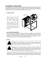
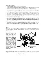
CPU Board
The CPU Board is part of the
Arcade Computer. Switch off
power to the VGM. Open and
remove the rear door. The Arcade
Computer is behind this door. Find
the four metal thumbscrews at the
top and bottom corners of the
computer case. To expose the
CPU Board, loosen, but don’t
remove these screws. Slide off the
back of the computer. Unscrew
and remove the circuit board
retention bars. Disconnect
external cables to the Video
Board, Network Board and Power
Filter Board. Remove the Video
Board, Network Board and Power
Filter Board. Disconnect the floppy
disk power and data cables at the
disk drive. Remove the floppy
drive-mounting bracket. Lift the
bracket and floppy drive out of the
cabinet. Set these aside for
reassembly.
Summary of Contents for Offroad Thunder
Page 3: ...iii...
Page 4: ...iv...
Page 20: ...Operation 2 6 NOTES...
Page 60: ...Diagnostic Audit Adjustment Menu System 3 40 NOTES...
Page 63: ...Wiring Circuit Information 4 3 Power Wiring Diagram...
Page 64: ...Wiring Circuit Information 4 4 Cabinet Wiring Diagram...
Page 65: ...Wiring Circuit Information 4 5 Player Panel Wiring Diagram...
Page 71: ...Wiring Circuit Information 4 11 BB12 Audio Amplifier Board Schematic 1 4...
Page 72: ...Wiring Circuit Information 4 12 BB12 Audio Amplifier Board Schematic 2 4...
Page 73: ...Wiring Circuit Information 4 13 BB12 Audio Amplifier Board Schematic 3 4...
Page 74: ...Wiring Circuit Information 4 14 BB12 Audio Amplifier Board Schematic 4 4...
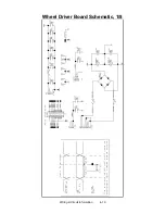
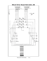
Page 79: ...Wiring Circuit Information 4 19 Wheel Driver Board Schematic 1 8...
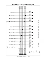
Page 80: ...Wiring Circuit Information 4 20 Wheel Driver Board Schematic 2 8...
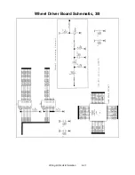
Page 81: ...Wiring Circuit Information 4 21 Wheel Driver Board Schematic 3 8...
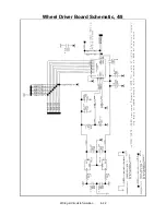
Page 82: ...Wiring Circuit Information 4 22 Wheel Driver Board Schematic 4 8...
Page 83: ...Wiring Circuit Information 4 23 Wheel Driver Board Schematic 5 8...
Page 84: ...Wiring Circuit Information 4 24 Wheel Driver Board Schematic 6 8...
Page 85: ...Wiring Circuit Information 4 25 Wheel Driver Board Schematic 7 8...
Page 86: ...Wiring Circuit Information 4 26 Wheel Driver Board Schematic 8 8...
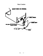
Page 99: ...Parts 7 3 Cabinet Rear View 01 10714 03 8326...
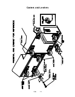
Page 101: ...Parts 7 5 Casters and Levelers...
Page 102: ...Parts 7 6 Rear Casters...
Page 105: ...Parts 7 9 Padlock 4320 01164 20B 01 11287 01 11286 4420 01141 00...
Page 106: ...Parts 7 10 Coin Door Assembly See Coin Door Application Table for Assembly Number...
Page 107: ...Parts 7 11 Pushbutton Assembly 20 9663 XX 20 10129 5 24 8880 24 8828...
Page 110: ...Parts 7 14 Optional Bill Validator...
Page 111: ...Parts 7 15 Cabinet Components...
Page 113: ...Parts 7 17 Casters and Leg Levelers...
Page 114: ...Parts 7 18 Throttle Assembly 20 10135 5014 12909 00...
Page 115: ...Parts 7 19 Fluorescent Lamp Assembly A 22506 20 10444 04 11241 1 24 8809 20 10481 2...
Page 117: ...Parts 7 21 Arcade Computer Mechanical Components...
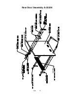
Page 131: ...Parts 7 35 Line Cord Installation Bracket AC Plug Assembly A 23089...
Page 149: ......