Setup 1-4
PRODUCT CONFIGURATION
•
Standalone Units
Each VGM (video game machine) is ready to play right out of the box. You can use the VGM Menu
System to set player variables in advance. Or you can leave these choices to players.
•
Linked Units
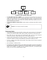
Linking allows players to compete against each other (on one course). Operator menus are the same
as in stand-alone VGMs. With a coupler and linking cable, you can connect two VGMs. (You can
connect up to four VGMs with the optional Hub Linking Kit.) You’ll find a coupler in the spare parts
envelope. Look in the cashbox. The linking cable is factory installed.
INSTALLATION & INSPECTION
WARNING: The cabinets are top-heavy. While moving the cabinets, don’t push against
plastic parts.
[ ] 1.
Remove and set aside items from the shipping containers. Remove all packing material. Inspect
for damage. Check the main cabinet exterior, the control section and the seat pedestal.
[ ] 2.
Remove the keys from the steering wheel. Unlock and open the coin, cash box, and rear doors.
You’ll find electrical cords, mechanical components, and VGM spare parts inside the cash box.
[ ] 3.
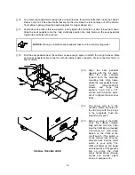
You can install an extra padlock to secure the rear door. You’ll find a hasp in the spare parts bag.
Remove the two lock bracket nuts from inside the cabinet, above the rear door opening. Slide the
hasp onto the bolts. Now the hasp should protrude from the hole in back of the cabinet. Reinstall
and tighten nuts.
CABINET SECURITY MODIFICATIONS
[ ] 4.
Modify the lock plate at the top of the rear door. Remove the bolts and nuts from the lock plate.
Rotate the plate so that the slot will be above the door. Reinstall and tighten the bolts and nuts.
Summary of Contents for Offroad Thunder
Page 3: ...iii...
Page 4: ...iv...
Page 20: ...Operation 2 6 NOTES...
Page 60: ...Diagnostic Audit Adjustment Menu System 3 40 NOTES...
Page 63: ...Wiring Circuit Information 4 3 Power Wiring Diagram...
Page 64: ...Wiring Circuit Information 4 4 Cabinet Wiring Diagram...
Page 65: ...Wiring Circuit Information 4 5 Player Panel Wiring Diagram...
Page 71: ...Wiring Circuit Information 4 11 BB12 Audio Amplifier Board Schematic 1 4...
Page 72: ...Wiring Circuit Information 4 12 BB12 Audio Amplifier Board Schematic 2 4...
Page 73: ...Wiring Circuit Information 4 13 BB12 Audio Amplifier Board Schematic 3 4...
Page 74: ...Wiring Circuit Information 4 14 BB12 Audio Amplifier Board Schematic 4 4...
Page 79: ...Wiring Circuit Information 4 19 Wheel Driver Board Schematic 1 8...
Page 80: ...Wiring Circuit Information 4 20 Wheel Driver Board Schematic 2 8...
Page 81: ...Wiring Circuit Information 4 21 Wheel Driver Board Schematic 3 8...
Page 82: ...Wiring Circuit Information 4 22 Wheel Driver Board Schematic 4 8...
Page 83: ...Wiring Circuit Information 4 23 Wheel Driver Board Schematic 5 8...
Page 84: ...Wiring Circuit Information 4 24 Wheel Driver Board Schematic 6 8...
Page 85: ...Wiring Circuit Information 4 25 Wheel Driver Board Schematic 7 8...
Page 86: ...Wiring Circuit Information 4 26 Wheel Driver Board Schematic 8 8...
Page 99: ...Parts 7 3 Cabinet Rear View 01 10714 03 8326...
Page 101: ...Parts 7 5 Casters and Levelers...
Page 102: ...Parts 7 6 Rear Casters...
Page 105: ...Parts 7 9 Padlock 4320 01164 20B 01 11287 01 11286 4420 01141 00...
Page 106: ...Parts 7 10 Coin Door Assembly See Coin Door Application Table for Assembly Number...
Page 107: ...Parts 7 11 Pushbutton Assembly 20 9663 XX 20 10129 5 24 8880 24 8828...
Page 110: ...Parts 7 14 Optional Bill Validator...
Page 111: ...Parts 7 15 Cabinet Components...
Page 113: ...Parts 7 17 Casters and Leg Levelers...
Page 114: ...Parts 7 18 Throttle Assembly 20 10135 5014 12909 00...
Page 115: ...Parts 7 19 Fluorescent Lamp Assembly A 22506 20 10444 04 11241 1 24 8809 20 10481 2...
Page 117: ...Parts 7 21 Arcade Computer Mechanical Components...
Page 131: ...Parts 7 35 Line Cord Installation Bracket AC Plug Assembly A 23089...
Page 149: ......


