


Parts 7-13
Dash Assembly A-23241 (Exploded)
4008-01100-08
4701-00005-00B
4427-01183-00
4008-01100-08
01-15080
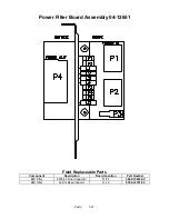
04-12729.3
14-8029
04-12730-1
4006-01100-16B
4700-00129-00B
4008-01100-08
04-12784.1
H-23218
4020-01100-20
03-9910-1
20-10189
20-10503.1
02-5351.1
4006-01100-08B
31-3419.1
20-10595
03-9933.2
20-10627
02-5279
20-10186
04-12730-2
02-5295-34
5795-15667-15
04-12759.1
5014-16301-00
4420-01141-00
4020-01100-20
20-10183
Summary of Contents for Offroad Thunder
Page 3: ...iii...
Page 4: ...iv...
Page 20: ...Operation 2 6 NOTES...
Page 60: ...Diagnostic Audit Adjustment Menu System 3 40 NOTES...
Page 63: ...Wiring Circuit Information 4 3 Power Wiring Diagram...
Page 64: ...Wiring Circuit Information 4 4 Cabinet Wiring Diagram...
Page 65: ...Wiring Circuit Information 4 5 Player Panel Wiring Diagram...
Page 71: ...Wiring Circuit Information 4 11 BB12 Audio Amplifier Board Schematic 1 4...
Page 72: ...Wiring Circuit Information 4 12 BB12 Audio Amplifier Board Schematic 2 4...
Page 73: ...Wiring Circuit Information 4 13 BB12 Audio Amplifier Board Schematic 3 4...
Page 74: ...Wiring Circuit Information 4 14 BB12 Audio Amplifier Board Schematic 4 4...
Page 79: ...Wiring Circuit Information 4 19 Wheel Driver Board Schematic 1 8...
Page 80: ...Wiring Circuit Information 4 20 Wheel Driver Board Schematic 2 8...
Page 81: ...Wiring Circuit Information 4 21 Wheel Driver Board Schematic 3 8...
Page 82: ...Wiring Circuit Information 4 22 Wheel Driver Board Schematic 4 8...
Page 83: ...Wiring Circuit Information 4 23 Wheel Driver Board Schematic 5 8...
Page 84: ...Wiring Circuit Information 4 24 Wheel Driver Board Schematic 6 8...
Page 85: ...Wiring Circuit Information 4 25 Wheel Driver Board Schematic 7 8...
Page 86: ...Wiring Circuit Information 4 26 Wheel Driver Board Schematic 8 8...
Page 99: ...Parts 7 3 Cabinet Rear View 01 10714 03 8326...
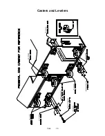
Page 101: ...Parts 7 5 Casters and Levelers...
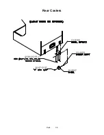
Page 102: ...Parts 7 6 Rear Casters...
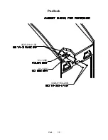
Page 105: ...Parts 7 9 Padlock 4320 01164 20B 01 11287 01 11286 4420 01141 00...
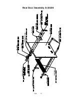
Page 106: ...Parts 7 10 Coin Door Assembly See Coin Door Application Table for Assembly Number...
Page 107: ...Parts 7 11 Pushbutton Assembly 20 9663 XX 20 10129 5 24 8880 24 8828...
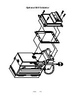
Page 110: ...Parts 7 14 Optional Bill Validator...
Page 111: ...Parts 7 15 Cabinet Components...
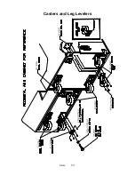
Page 113: ...Parts 7 17 Casters and Leg Levelers...
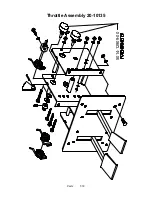
Page 114: ...Parts 7 18 Throttle Assembly 20 10135 5014 12909 00...
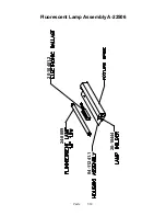
Page 115: ...Parts 7 19 Fluorescent Lamp Assembly A 22506 20 10444 04 11241 1 24 8809 20 10481 2...
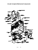
Page 117: ...Parts 7 21 Arcade Computer Mechanical Components...
Page 131: ...Parts 7 35 Line Cord Installation Bracket AC Plug Assembly A 23089...
Page 149: ......