


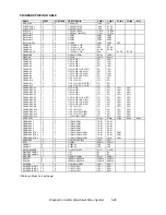
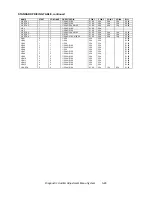


Diagnostic, Audit & Adjustment Menu System 3-19
Operator Menu (continued)
Adjustments Menu (continued)
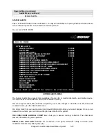
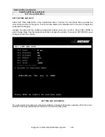
Linked-Play Adjustments Menu
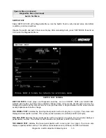
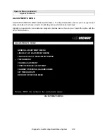
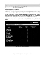
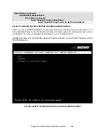
LINKED PLAY ADJUSTMENTS MENU
Select LINKED PLAY ADJUSTMENTS MENU at the Adjustments Menu. The Linked Play Adjustments
Menu allows you to set the game cabinet network identity. After you cable the linked cabinets, use this
menu to set up linked play.
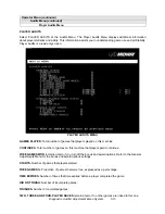
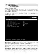
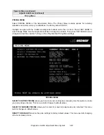
Highlight an option with the middle two diagnostic buttons inside the coin door. Press TEST MODE to
enter Change Mode. Use the diagnostic switches to change the variable. Then press TEST MODE to save
changes and exit the variable.
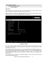
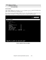
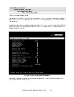
LINKED-PLAY ADJUSTMENTS MENU
Before proceeding, bring up the Linked Play Adjustments Menu on all linked cabinets.
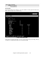
LINKED PLAY. After you link a cabinet to other games, turn on LINKED PLAY. Now game electronics can
communicate with other cabinets. To prohibit linked play, turn off the feature. The factory default is off.
UNIT ID determines the game’s address. Each linked game must have a unique number. Never use the
same address for two cabinets. Sequence isn’t important. The factory default ID is 1.
REINITIALIZE. After selecting the ID, exit the Menu System. Shut down each linked cabinet for one
minute. (Leave the computers switched on.) Then restore power to all cabinets. The cabinets should
initialize in Linked Mode. Verify linked operation by playing some linked games.
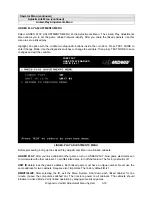
FREE PLAY
LINKED PLAY ENABLED
UNIT ID (1-4): 1
Summary of Contents for Offroad Thunder
Page 3: ...iii...
Page 4: ...iv...
Page 20: ...Operation 2 6 NOTES...
Page 60: ...Diagnostic Audit Adjustment Menu System 3 40 NOTES...
Page 63: ...Wiring Circuit Information 4 3 Power Wiring Diagram...
Page 64: ...Wiring Circuit Information 4 4 Cabinet Wiring Diagram...
Page 65: ...Wiring Circuit Information 4 5 Player Panel Wiring Diagram...
Page 71: ...Wiring Circuit Information 4 11 BB12 Audio Amplifier Board Schematic 1 4...
Page 72: ...Wiring Circuit Information 4 12 BB12 Audio Amplifier Board Schematic 2 4...
Page 73: ...Wiring Circuit Information 4 13 BB12 Audio Amplifier Board Schematic 3 4...
Page 74: ...Wiring Circuit Information 4 14 BB12 Audio Amplifier Board Schematic 4 4...
Page 79: ...Wiring Circuit Information 4 19 Wheel Driver Board Schematic 1 8...
Page 80: ...Wiring Circuit Information 4 20 Wheel Driver Board Schematic 2 8...
Page 81: ...Wiring Circuit Information 4 21 Wheel Driver Board Schematic 3 8...
Page 82: ...Wiring Circuit Information 4 22 Wheel Driver Board Schematic 4 8...
Page 83: ...Wiring Circuit Information 4 23 Wheel Driver Board Schematic 5 8...
Page 84: ...Wiring Circuit Information 4 24 Wheel Driver Board Schematic 6 8...
Page 85: ...Wiring Circuit Information 4 25 Wheel Driver Board Schematic 7 8...
Page 86: ...Wiring Circuit Information 4 26 Wheel Driver Board Schematic 8 8...
Page 99: ...Parts 7 3 Cabinet Rear View 01 10714 03 8326...
Page 101: ...Parts 7 5 Casters and Levelers...
Page 102: ...Parts 7 6 Rear Casters...
Page 105: ...Parts 7 9 Padlock 4320 01164 20B 01 11287 01 11286 4420 01141 00...
Page 106: ...Parts 7 10 Coin Door Assembly See Coin Door Application Table for Assembly Number...
Page 107: ...Parts 7 11 Pushbutton Assembly 20 9663 XX 20 10129 5 24 8880 24 8828...
Page 110: ...Parts 7 14 Optional Bill Validator...
Page 111: ...Parts 7 15 Cabinet Components...
Page 113: ...Parts 7 17 Casters and Leg Levelers...
Page 114: ...Parts 7 18 Throttle Assembly 20 10135 5014 12909 00...
Page 115: ...Parts 7 19 Fluorescent Lamp Assembly A 22506 20 10444 04 11241 1 24 8809 20 10481 2...
Page 117: ...Parts 7 21 Arcade Computer Mechanical Components...
Page 131: ...Parts 7 35 Line Cord Installation Bracket AC Plug Assembly A 23089...
Page 149: ......