Diagnostic, Audit & Adjustment Menu System 3-2
MENU SYSTEM
WHAT IS THE MENU SYSTEM?
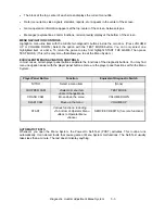
The game’s Menu System is a series of auditing, game adjustment and diagnostic screens. You can
easily access and apply these screens to optimize game performance. For instance…
•
Use game audits screens to assess game performance.
•
Use adjustment screens to help you to customize game performance. For instance, you can restore
factory default game settings. You can also calibrate player controls for accuracy.
•
Use diagnostic screens to verify proper equipment operation.
ACTIVATING THE MENU SYSTEM
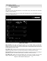
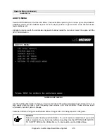
Open the coin door. Find the TEST MODE switch inside. Press TEST MODE to invoke the Menu System.
The game system responds by exiting Game Mode and entering Diagnostic Mode. The system runs a
brief self-test, and then displays the Operator Menu. The Operator Menu is the opening screen of the
Menu System.
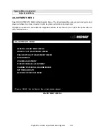
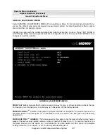
Game audits, adjustments and diagnostics are line items on the Operator Menu. Selecting an item opens
its submenu. Every submenu presents various options that you
may act upon.
OPERATOR MENU
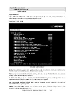
MENU LAYOUT
Menus differ, but related information tends to occupy the same screen locations.
OFF ROAD THUNDER
1999 Midway Home Entertainment Inc.
All rights reserved.
OFF ROAD THUNDER is a trademark of Midway Home Entertainment Inc.
MIDWAY is a trademark of Midway Games Inc.
Summary of Contents for Offroad Thunder
Page 3: ...iii...
Page 4: ...iv...
Page 20: ...Operation 2 6 NOTES...
Page 60: ...Diagnostic Audit Adjustment Menu System 3 40 NOTES...
Page 63: ...Wiring Circuit Information 4 3 Power Wiring Diagram...
Page 64: ...Wiring Circuit Information 4 4 Cabinet Wiring Diagram...
Page 65: ...Wiring Circuit Information 4 5 Player Panel Wiring Diagram...
Page 71: ...Wiring Circuit Information 4 11 BB12 Audio Amplifier Board Schematic 1 4...
Page 72: ...Wiring Circuit Information 4 12 BB12 Audio Amplifier Board Schematic 2 4...
Page 73: ...Wiring Circuit Information 4 13 BB12 Audio Amplifier Board Schematic 3 4...
Page 74: ...Wiring Circuit Information 4 14 BB12 Audio Amplifier Board Schematic 4 4...
Page 79: ...Wiring Circuit Information 4 19 Wheel Driver Board Schematic 1 8...
Page 80: ...Wiring Circuit Information 4 20 Wheel Driver Board Schematic 2 8...
Page 81: ...Wiring Circuit Information 4 21 Wheel Driver Board Schematic 3 8...
Page 82: ...Wiring Circuit Information 4 22 Wheel Driver Board Schematic 4 8...
Page 83: ...Wiring Circuit Information 4 23 Wheel Driver Board Schematic 5 8...
Page 84: ...Wiring Circuit Information 4 24 Wheel Driver Board Schematic 6 8...
Page 85: ...Wiring Circuit Information 4 25 Wheel Driver Board Schematic 7 8...
Page 86: ...Wiring Circuit Information 4 26 Wheel Driver Board Schematic 8 8...
Page 99: ...Parts 7 3 Cabinet Rear View 01 10714 03 8326...
Page 101: ...Parts 7 5 Casters and Levelers...
Page 102: ...Parts 7 6 Rear Casters...
Page 105: ...Parts 7 9 Padlock 4320 01164 20B 01 11287 01 11286 4420 01141 00...
Page 106: ...Parts 7 10 Coin Door Assembly See Coin Door Application Table for Assembly Number...
Page 107: ...Parts 7 11 Pushbutton Assembly 20 9663 XX 20 10129 5 24 8880 24 8828...
Page 110: ...Parts 7 14 Optional Bill Validator...
Page 111: ...Parts 7 15 Cabinet Components...
Page 113: ...Parts 7 17 Casters and Leg Levelers...
Page 114: ...Parts 7 18 Throttle Assembly 20 10135 5014 12909 00...
Page 115: ...Parts 7 19 Fluorescent Lamp Assembly A 22506 20 10444 04 11241 1 24 8809 20 10481 2...
Page 117: ...Parts 7 21 Arcade Computer Mechanical Components...
Page 131: ...Parts 7 35 Line Cord Installation Bracket AC Plug Assembly A 23089...
Page 149: ......


