Chapter 6 Functional principle
6.1 Internal processing of the measurement values
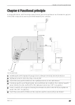
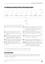
Diagram of the internal processing of the measurement values
1 Increasing the resolution by oversampling
1)
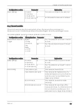
6 Adds the values entered via the "Trim" and
"Sensor offset" configuration parameters to
the measurement value (see "Trim/sensor
offset module" on page 31).
1)2)
2 Decay module to summarise several
measurement values (see "Decay module" on
page 29)
1)
7 Monitoring of the alarm limits and trigger
levels (see "Alarm/trigger module" on page
32)
3 Temperature compensation to adjust any
thermal influences (see "Temperature
compensation module" on page 30).
1)2)
8 Recording of the measurement values (see
4 Monitoring of the measurement range limits
(see "Overflow module" on page 30)
1)2)
9 This module chain is started at the time of
every measurement and is completed once.
5 Rescaling from the raw value to the
measurement value (see "Scale module" on
page 31)
10 Adding up the pulses at universal input 1 (see
"Counter module" on page 34). This module
is operated permanently if "Cnt.Day" or
"Cnt.Intrvl." channel mode is selected.
1)
These modules are skipped if "Cnt.Day" and "Cnt.Intrvl." channel modes are used
2)
These modules are only processed in channel modes "0...20mA" and "4...20mA".
6.1.1 Decay module
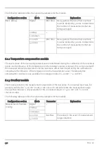
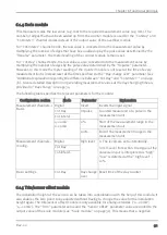
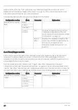
The decay module is designed to summarise several measurement values. The average value is
calculated over a specified time period. The decay module is not available for "Cnt.Day" and
"Cnt.Intervl." channel modes.
Rev. 02
29
Summary of Contents for 305001
Page 2: ......
Page 8: ......
Page 9: ...Chapter 2 Declaration of conformity Chapter 2 Declaration of conformity Rev 02 9 ...
Page 10: ......
Page 11: ...Chapter 3 Ex certification Chapter 3 Ex certification Rev 02 11 ...
Page 12: ...12 Rev 02 ...
Page 13: ...Chapter 3 Ex certification Rev 02 13 ...
Page 14: ......
Page 26: ......
Page 38: ......
Page 64: ......
Page 84: ......
Page 106: ......
Page 108: ......
Page 126: ......


