


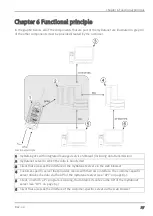


Chapter 6 Functional principle
6.1.4 Scale module
This module rescales the raw value (e.g. mA) to the required measurement value (e.g. mm). The
number of edges that have been added up from the counter module is used for the "Cnt.Day" and
"Cnt.Intervl." channel modes instead of the output value of the overflow module.
For "Cnt.Intervl." channel mode, the raw value is converted into the measurement value by
multiplying the number of edges that have been added up by the pulse value determined by the
"Impulse" parameter. The meter reading of the counter module is then reset.
For "Cnt.Day" channel mode, the raw value is also converted into the measurement value by
multiplying the number of edges by the pulse value determined by the "Impulse" parameter.
However, in this mode the meter reading of the counter module is not reset at the time of every
measurement but is instead reset at the time specified via the "Day change over" parameter (see
"Additional explanation regarding the difference between "Cnt.Day" and "Cnt.Intervl."" on page
72). A more detailed description on generating measurement values at the day changing time are
provided in "Day change" on page 34.
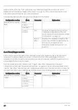
The following table specifies the relevant parameters for the module:
Configuration section
Mode
Parameter
Explanation
Measurement channels ->
Basis
Digital
Invert
Inverts the input signal
Cnt.Day
Impulse
Counted measurand of a pulse in the
measurement unit
Cnt.Intervl.
4-20mA
0-20mA
0%
Start of the measurement range in the
measurement unit
100%
End of the measurement range in the
measurement unit
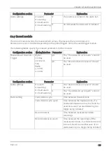
Measurement channels -
>Config.
Digital
High level
0: The levels are set automatically.
> 0mV: Level from which the signal at the
universal input is interpreted as "high".
"low" is detected at the "high level" -
10%.
Cnt.Day
Cnt.Intervl.
Basic settings
Cnt.Day
Day change
over
Reset time of the day counter
6.1.5 Trim/sensor offset module
The installation height of the sensor can be taken into consideration with the help of this module. It
also enables the zero point to be adjusted without having to change the value for the installation
height again. The trim/sensor offset module is only available for analogue modes ("0...20mA",
"4...20mA"). The "Trim" parameter value and the "Sensor offset" parameter value are added to the
output value of the scale module (see "Scale module" on page 31). This means that a negative
Rev. 02
31
Summary of Contents for 305001
Page 2: ......
Page 8: ......
Page 9: ...Chapter 2 Declaration of conformity Chapter 2 Declaration of conformity Rev 02 9 ...
Page 10: ......
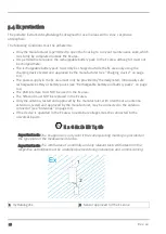
Page 11: ...Chapter 3 Ex certification Chapter 3 Ex certification Rev 02 11 ...
Page 12: ...12 Rev 02 ...
Page 13: ...Chapter 3 Ex certification Rev 02 13 ...
Page 14: ......
Page 26: ......
Page 38: ......
Page 64: ......
Page 84: ......
Page 106: ......
Page 108: ......
Page 126: ......


