


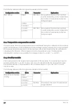
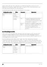


The following table specifies the relevant parameters for the module:
Configuration section
Mode
Parameter
Explanation
Basic setting
Digital
Filter time
Decay period. The time that is set here
must be divided by 300 ms to determine
the number of measurements that are
being averaged.
Cnt.Day
---
---
Cnt.Intervl.
0-20 mA
Filter time
Decay period. The time that is set here
must be divided by 300 ms to determine
the number of measurements that are
being averaged.
4-20 mA
6.1.2 Temperature compensation module
The exact values of the measuring resistances are determined during the calibration of the universal
inputs. As the influence of the temperature on the resistance values is known, this can be used with
the measured ambient temperature and the resistance offset determined during the calibration to
compensate the influence of the temperature on the measurement value. The temperature
compensation module is only available for analogue modes ("0...20mA", "4...20mA").
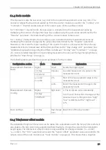
6.1.3 Overflow module
This module monitors the measurement range limits of the raw value. If a universal input was, for
example, switched to "4-20 mA" mode, a raw value of 2 mA will violate the measurement range.
The overflow module is only available for the 2 universal inputs in "4-20 mA" and "0-20 mA"
channel modes.
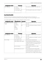
The following table specifies the relevant parameters for the module:
Configuration section
Mode
Parameter
Explanation
Measurement channels -
>Config.
Digital
---
---
Cnt.Day
Cnt.Intervl.
0-20 mA
Overflow
Procedure in the event of measurement
range violations
4-20 mA
30
Rev. 02
Summary of Contents for 305001
Page 2: ......
Page 8: ......
Page 9: ...Chapter 2 Declaration of conformity Chapter 2 Declaration of conformity Rev 02 9 ...
Page 10: ......
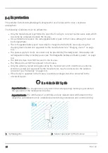
Page 11: ...Chapter 3 Ex certification Chapter 3 Ex certification Rev 02 11 ...
Page 12: ...12 Rev 02 ...
Page 13: ...Chapter 3 Ex certification Rev 02 13 ...
Page 14: ......
Page 26: ......
Page 38: ......
Page 64: ......
Page 84: ......
Page 106: ......
Page 108: ......
Page 126: ......


