Chapter 12 Maintenance
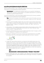
12.7.2 Zero point adjustment using the ALOHA data
The zero point adjustment is used to compensate shiftings of the zero point. The basic calibration
of the device is not changed by the zero point adjustment.
Important note: As the ALOHA data is only generated every 3 seconds (see "ALOHA trans-
mission mode" on page 35), this procedure is only suitable if the fill level is as constant as
possible during the zero point adjustment.
The zero point adjustment is used to compensate shiftings of the zero point. The basic calibration
of the device is not changed by the zero point adjustment.
Note: During the zero point adjustment, it is recommended to increase the duration of the ALOHA connection via
the "Aloha duration" parameter that is located in the "Basic settings" configuration section (see "Basic setting"
on page 80).
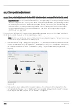
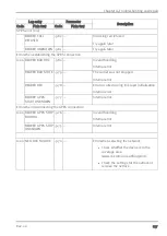
1. First of all, enter the installation height of the sensor for the required universal input via the
"Sensor offset" parameter of the "Measurement channels" configuration section (see "Meas-
urement channels" on page 67). The parameter is located in the "Basic" tab of the con-
figuration section.
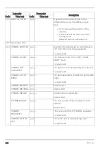
2. Check that the "Trim" parameter, that specifies the offset for the zero point, is set to 0 for the
required universal input. This parameter is also located in the "Basic" tab of the "Meas-
urement channels" configuration section.
3. Activate the ALOHA transmission mode (see "ALOHA transmission mode" on page 35) so that
the site configuration is transferred to the myDatalog2Ex .
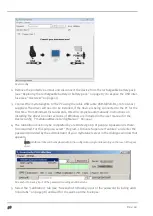
4. Wait until it is indicated in the list of measurement instruments that the device is in ALOHA
transmission mode. This is indicated by a speech bubble with the "Aloha" inscription.
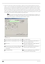
5. Compare the measured fill level with the incoming data in the ALOHA data window of the
myDatanet server, which can be accessed by clicking on the speech bubble with the "Aloha"
inscription (see "myDatanet Server Manual " 805002). The difference between the measured
fill level and the displayed fill level must now be entered as the "Trim" parameter. It should be
noted that the difference must be entered with a negative prefix if the displayed fill level is
higher than the measured fill level (see "Additional explanation on the zero point adjustment
and installation height of the sensor" on page 70).
Note:
Measurement value = scaled measurement value + "Trimming" + "Sensor offset"
6. After saving the entry for the "Trim" parameter, check whether the measured fill level matches
the incoming ALOHA data. Initiate ALOHA transmission mode again if it has been completed in
the meantime.
Rev. 02
105
Summary of Contents for 305001
Page 2: ......
Page 8: ......
Page 9: ...Chapter 2 Declaration of conformity Chapter 2 Declaration of conformity Rev 02 9 ...
Page 10: ......
Page 11: ...Chapter 3 Ex certification Chapter 3 Ex certification Rev 02 11 ...
Page 12: ...12 Rev 02 ...
Page 13: ...Chapter 3 Ex certification Rev 02 13 ...
Page 14: ......
Page 26: ......
Page 38: ......
Page 64: ......
Page 84: ......
Page 106: ......
Page 108: ......
Page 126: ......

