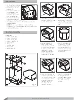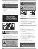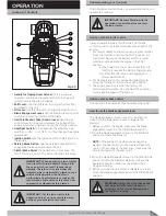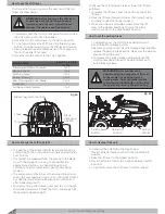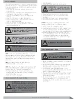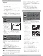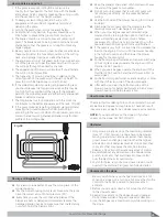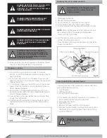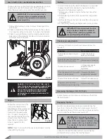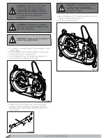
The lawn tractor can be lifted into a perpendicular position
to provide access to the lower part of the machine.
3ODFHWKHODZQWUDFWRURQDVROLG´UPDQGµDWJURXQG
5HPRYHWKHEDWWHU\LQRUGHUWRSUHYHQWOHDNDJHRIWKH
electrolyte.
2. Check to determine if the fuel tank does not have more
than one liter of fuel in the tank. If so, drain the fuel tank.
3. Check to ensure the lawn tractor is well supported and
balanced on the container handles which are located on
the lower side of the plate.
In order to maximize the life of the battery it is essential
WRNHHSLWFDUHIXOO\PDLQWDLQHGE\KDYLQJWKHEDWWHU\
FKDUJHGLQWKHIROORZLQJVLWXDWLRQV
%HIRUHXVLQJWKHODZQWUDFWRUIRUWKH´UVWWLPHDIWHU
purchase.
%HIRUHOHDYLQJWKHPDFKLQHXQXVHGIRUDORQJSHULRG
of time.
%HIRUHVWDUWLQJXSWKHODZQWUDFWRUDIWHUDORQJSHULRG
of unused time.
$µDWEDWWHU\PXVWEHUHFKDUJHGDVVRRQDVSRVVLEOH
/DZQ7UDFWRU5HDU'LVFKDUJH
30
Lawn tractor into a perpendicular position
Battery
IMPORTANT:
It is recommended that a
minimum of two competent people be
involved in this operation to assure the
necessary safety.
IMPORTANT:
Recharging must be done
using a battery charger at a constant
voltage. Other recharging systems can
irreversibly damage the battery.
DANGER: IT IS CRITICAL THAT THE LAWN
TRACTOR IS WELL BALANCED AND OFFERS
GOOD STABILITY BEFORE COMMENCING
ANY TYPE OF WORK ON THE MACHINE.
AVOID ANY OPERATIONS WHICH MAY
ACCIDENTALLY CAUSE THE MACHINE TO
FALL OVER.
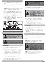
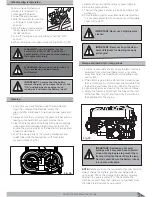
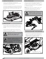
Engine
Follow the instructions in the
manual for operation and
PDLQWHQDQFHRIWKHHQJLQHDLU
DQGIXHO´OWHURLOH[FKDQJH
FOHDQLQJRIWKHVSDUNSOXJV
HWF7RGUDLQWKHHQJLQHRLO
unscrew the stopper from the
RLOGUDLQKROH)LJDQG
allow the oil to empty itself
into a prepared tank or
receiver.
NOTE:
Check to ensure that the seal is positioned correctly
ZKHQUH´WWLQJWKHSOXJ
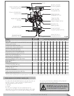
Checks and adjustments
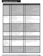
Summary of the main situations where work may be
UHTXLUHG
P r o b le m
R e c o m m e n d a t io n
The blades are be
J
innin
J
to
vibrate
Check the bolts or
balance the blades
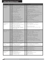
The blades tear the
J
rass and
the lawn becomes yellow
Blades need sharpenin
J
There is an uneven cut
Cuttin
J
deck needs
adjustment and
ali
J
nment
The en
J
a
J
ement of the blades
seems to be abnormal
Re
J
ulate the blade
en
J
a
J
ement adjuster
The machine does not brake
Adjust the brake sprin
J
The
J
rass-catcher jumps
around and tends to open up.
Adjust the sprin
J
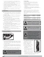
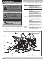
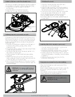
Replacing the lamps (12V, 10/15 W)
Rotate the lamps anti-clockwise and remove them from
the lamp holder .
Replacing the fuse
Electric circuits and electronics are protected by the
IXVH$7KLVSURWHFWVWKHPDLQDQGSRZHUFLUFXLWVRI
the electronic board. If this fuse is blown, the lawn tractor
will stop and the dashboard will switch off.
IMPORTANT:
A fuse which has blown
must always be replaced immediately by
a fuse of the same type and ampere rating.
Never replace with one of another rating.
The capacity of the fuse is indicated on
the fuse itself.
&RQVXOWD/LFHQVHG6HUYLFH&HQWUHLI\RXDUHKDYLQJ
SUREOHPV´QGLQJRXWZK\WKHIXVHKDVEORZQ
Fig 39
Stopper
Fig 40
Summary of Contents for Gizmow T130
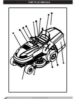
Page 12: ...KNOW YOUR PRODUCT Lawn Tractor Rear Discharge 12 Decals and Labels ...
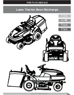
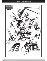
Page 37: ...PARTS SCHEDULE Lawn Tractor Rear Discharge 37 T130 T140 T160 T180 Lawn Tractor Rear Discharge ...
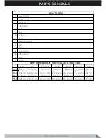
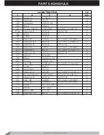
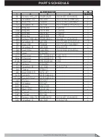
Page 38: ...PARTS SCHEDULE Lawn Tractor Rear Discharge 38 ...
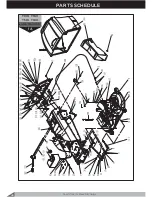
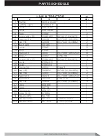
Page 40: ...Lawn Tractor Rear Discharge 40 PARTS SCHEDULE T130 T160 T140 T180 LAWN TRACTOR 1A ...
Page 44: ...T130 T160 T140 T180 LAWN TRACTOR 1B PARTS SCHEDULE Lawn Tractor Rear Discharge 44 ...
Page 49: ...T130 T160 LAWN TRACTOR 1C Lawn Tractor Rear Discharge 49 PARTS SCHEDULE ...
Page 50: ...T140 T180 LAWN TRACTOR 1C PARTS SCHEDULE Lawn Tractor Rear Discharge 50 ...
Page 53: ...T130 T160 T140 T180 LAWN TRACTOR 1D Lawn Tractor Rear Discharge 53 PARTS SCHEDULE ...
Page 56: ...T130 T160 T140 T180 CUTTING DECK 2 PARTS SCHEDULE Lawn Tractor Rear Discharge 56 ...
Page 60: ...T130 T160 FRONT AXLE 7 PARTS SCHEDULE Lawn Tractor Rear Discharge 60 ...
Page 61: ...T140 T180 FRONT AXLE 7 Lawn Tractor Rear Discharge 61 PARTS SCHEDULE ...
Page 63: ...T130 T160 T140 T180 LIFTING LEVER 11 Lawn Tractor Rear Discharge 63 PARTS SCHEDULE ...
Page 65: ...T130 T160 T140 T180 HUB 14 Lawn Tractor Rear Discharge 65 PARTS SCHEDULE ...
Page 67: ...T130 T160 T140 T180 REAR AXLE 15A Lawn Tractor Rear Discharge 67 PARTS SCHEDULE ...
Page 69: ...T130 T160 T140 T180 REAR AXLE 15B Lawn Tractor Rear Discharge 69 PARTS SCHEDULE ...
Page 73: ...T130 T160 T140 T180 HOOD 24 Lawn Tractor Rear Discharge 73 PARTS SCHEDULE ...
Page 75: ...T130 T160 T140 T180 PANEL 25 Lawn Tractor Rear Discharge 75 PARTS SCHEDULE ...
Page 77: ...T130 T160 T140 T180 ELECTRICAL SYSTEM 27 Lawn Tractor Rear Discharge 77 PARTS SCHEDULE ...
Page 78: ...T130 T160 T140 T180 ELECTRICAL SYSTEM 27a PARTS SCHEDULE Lawn Tractor Rear Discharge 78 ...
Page 80: ...T130 T160 T140 T180 SEAT 32 PARTS SCHEDULE Lawn Tractor Rear Discharge 80 ...
Page 82: ...T130 T160 T140 T180 BUNKER 34 PARTS SCHEDULE Lawn Tractor Rear Discharge 82 ...
Page 84: ...T130 T160 T140 T180 GEAR SHIFTING 35 PARTS SCHEDULE Lawn Tractor Rear Discharge 84 ...
Page 86: ...T130 T160 T140 T180 SEGMENT 36 PARTS SCHEDULE Lawn Tractor Rear Discharge 86 ...
Page 88: ...T130 T160 T140 T180 PLATE 37 PARTS SCHEDULE Lawn Tractor Rear Discharge 88 ...
Page 90: ...T130 T160 T140 T180 DECALS 38 PARTS SCHEDULE Lawn Tractor Rear Discharge 90 ...

