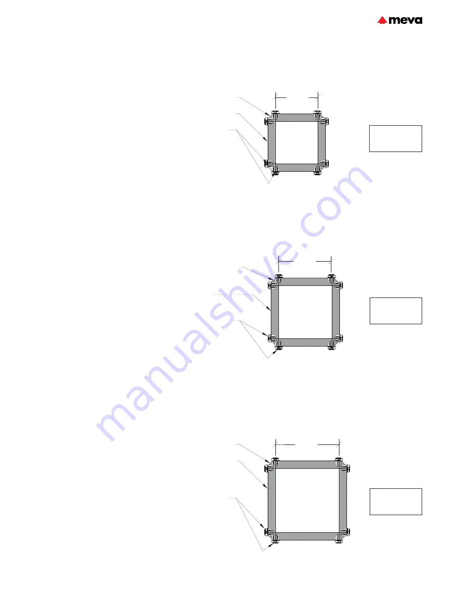
Meva MevaLite Technical Instruction Manual Download Page 29

MevaLite

ML-29

Columns

Columns with Standard Panels 
and Outside Corners:

Columns can also be formed 
using standard panels and outside 
corners. To form columns with 
sizes in between the MevaLite 
panel widths, the next largest 
panel size is used and the forms 
are furred out on the inside.

Columns can only be formed with 
panels oriented vertically (panel 
cross members horizontal).
The outside corner connections 
require more assembly locks than 
standard panel connections. The 
connection requirements and 
maximum allowable concrete 
pressure depend on the column 
size (with rectangular columns 
the longer side controls) - see 
Figures 29.1 - 29.3.

*For columns > 30" to  ≤ 36" 
1350 psf may be achieved with the 
addition of reinforcing rails. 
Refer to MEVA engineering for 
guidance.

Fig. 29.1 Column sizes up to 24"

Locks required at 
outside corner joints:
  9' panel - 7 locks
  6' panel - 5 locks
  4' panel - 4 locks
  3' panel - 3 locks

≤ 24"

≤ 30"

Outside corner, typ.

MevaLite panel, typ.

Outside corner, typ.

MevaLite 
multi-purpose panel, typ.

Locks required at 
outside corner joints:
  9' panel - 8 locks
  6' panel - 6 locks
  4' panel - 4 locks
  3' panel - 3 locks

Fig. 29.2 Column sizes up to 30"

Maximum allowable 
concrete pressure = 
1350 psf. 

Maximum allowable 
concrete pressure = 
1350 psf. 

Fig. 29.3 Column sizes up to 36"

Locks required at 
outside corner joints:
  9' panel - 8 locks
  6' panel - 6 locks
  4' panel - 4 locks
  3' panel - 3 locks

≤ 36"

Outside corner, typ.

MevaLite panel, typ.

Maximum allowable 
concrete pressure = 
1100 psf. *

MPP

MPP

MPP

MPP

Wall formwork

Technical Instruction Manual / June 2022

Summary of Contents for MevaLite

Page 1: ...Technical Instruction Manual June 2022 MevaLite...

Page 2: ...vaLite panels are available in 4 different heights 9 6 4 and 3 and in 5 different widths 3 2 1 6 1 0 and 6 In addition 2 6 wide multi purpose panels are available in each height These panels have mult...

Page 3: ...ed or weakened due to wear or corrosion Never oil or wax MEVA assembly locks The user must ensure the stability of all components during all phases of construction For gang formwork the user should al...

Page 4: ...multi function profiles have Dywidag threaded nuts inside which allow for fast and safe attachment of accessory parts Fig 4 7 The tie off bar allows safe working on the formwork Under no circumstances...

Page 5: ...drilling selected tie holes at exact locations Plug the unneeded tie holes with Plug D27 30 The 9 panels have 3 multi adjustment profiles the 6 and 4 panels have 2 multi adjustment profiles and the 3...

Page 6: ...the release of highly toxic dioxin is avoided which is released in the pro cess of burning plywood that is bonded with phenolic resin Used or damaged alkus plastic sheets can be recycled into the sam...

Page 7: ...hown in Figure 7 4 Additional locks are required for columns and outside corners refer to respective sections for details Panels with aluminum or wood fillers in between are connected with the Uni ass...

Page 8: ...2 500 2990158 Articuated flange nut 15 120 29 900 10 Purchase 5 8 15mm Threadbar 19 1 2 500 2990140 5 8 15mm Neoprene Waterstop 2 500 2990237 Fig 8 1 5 8 15mm Taper Tie 1 to 3 4 Fig 8 2 5 8 15mm Thre...

Page 9: ...zontal and vertical assembly Uniform joint grid Vertical joints For 3 high panels you need just one 5 8 15 mm tie The 4 and 6 high panels require 2 ties and the 9 high panels require 3 ties In general...

Page 10: ...y Uniform joint grid Vertical joints For 3 high panels you need just one 5 8 15 mm tie The 4 and 6 high panels require 2 ties and the 9 high panels require 3 ties In general all tie positions pre dete...

Page 11: ...lected tie holes at exact locations Plug the unneeded tie holes with Plug D27 30 The 9 panels have 3 multi adjustment profiles the 6 and 4 panels have 2 multi adjustment profiles and the 3 panel has 1...

Page 12: ...have to be used These flange nuts can be easily installed by using a hammer or a spanner In order to secure the fo rm work against uplift it has to be anchored to the ground using shoe plates or othe...

Page 13: ...w is 3 high If a walkway bracket is attached to the top panel install ties in the upper tie holes For stacked panel conditions where the top of concrete is 1 above the panel below Fig 13 2 and for all...

Page 14: ...nt wall thicknesses Steel rails may be required depending on the filler tie configuration see the Fillers section and the wall thickness MevaLite Outside Corners The outside corners Fig 14 5 14 6 are...

Page 15: ...thicknesses 12 but 18 more locks are required at the outside corner connections Additional locks are also required on the adjacent panel joints near the corner Fig 15 2 Fig 15 1 Walls up to 12 thick F...

Page 16: ...thick example corner elevation Locks required at all panel joints within 9 of outside corner 9 panel 6 locks 6 panel 4 locks 4 panel 3 locks 3 panel 2 locks 18 24 3 3 IC O C Flange screw 18 rail pane...

Page 17: ...ners for walls from 12 to 15 thick Fig 17 3 17 4 The maximum allowable concrete pressure is 1350 psf Additional locks are required at the panel joints within 7 of the corner Both methods create a tigh...

Page 18: ...ollowed by a few hammer blows If wood fillers are needed the panel profiles are connected using Uni assembly locks Side length of articulated outside corner 5 Side length of articulated inside corner...

Page 19: ...21 3 22 6 23 9 25 2 26 5 80 16 5 17 7 18 9 20 1 21 3 22 5 23 7 24 9 85 15 7 16 8 17 9 19 0 20 1 21 2 22 3 23 4 90 15 0 16 0 17 0 18 0 19 0 20 0 21 0 22 0 95 14 3 15 2 16 2 17 1 18 0 18 9 19 8 20 7 100...

Page 20: ...30 8 32 0 33 2 34 4 35 6 85 24 5 25 6 26 6 27 7 28 8 29 9 31 0 32 1 33 2 90 23 0 24 0 25 0 26 0 27 0 28 0 29 0 30 0 31 0 95 21 7 22 6 23 5 24 4 25 3 26 2 27 2 28 1 29 0 100 20 4 21 3 22 1 22 9 23 8 24...

Page 21: ...ork is ready for the next pour for details please see next pages Be sure to tape all seams on each corner and plug all unused tie holes prior to oiling the face to keep concrete from filling the inner...

Page 22: ...mechanism of the corner is pulled all the way to the top the stripping corner is retracted and is in its stripped position Fig 22 5 Description Ref No ML stripping corners 9 22 508 00 6 22 508 10 4 22...

Page 23: ...is reset to the expanded pouring position The wedge can be driven in at the top of the stripping corner with a few hammer blows for assistence in resetting the corner to expanded position Be sure to...

Page 24: ...ice at the top of the stripping corner Connect the retract and reset tool to the stripping corner with the head bolt and cotter pin that are both integrated into the tensioning screw of the retract an...

Page 25: ...es the stripping corner and separates the shaft formwork from the concrete walls Fig 25 3 and Fig 25 4 Description Ref No ML stripping corners 9 22 508 00 6 22 508 10 4 22 508 20 Stripping corner retr...

Page 26: ...is pushed all the way down the corner is reset into place Remove the tool and reinstall the wedge Description Ref No ML stripping corners 9 22 508 00 6 22 508 10 4 22 508 20 Stripping corner retract a...

Page 27: ...lamps to keep the corners from separating The ML stripping corner can also be used for stripping of panels between corners inside a structure In this case the stripping corner is used to reduce the co...

Page 28: ...19 with rectangular columns the longer side controls Description Ref No ML multi purpose panels 9 x2 5 22 500 25 6 x2 5 22 501 25 4 x2 5 22 502 25 3 x2 5 22 503 25 EA assembly lock 29 205 50 Uni asse...

Page 29: ...6 1350 psf may be achieved with the addition of reinforcing rails Refer to MEVA engineering for guidance Fig 29 1 Column sizes up to 24 Locks required at outside corner joints 9 panel 7 locks 6 panel...

Page 30: ...section for additional filler information and requirements Fillers Up to 6 5 Wide Steel rails are required at each tie hole elevation They are installed either between two ties Fig 30 2 or cantilever...

Page 31: ...nded loads Tensile load transfer must be considered when fillers are located near bulkheads or outside corners Additional fasteners bracing or struts may be required Fig 31 1 Rails supporting fillers...

Page 32: ...irements It may be necessary to utilize threadbar ties in some corner locations when other tie systems are used so they can be shifted far enough to eliminate interferences In some cases the need for...

Page 33: ...rete pressure of 1350 psf Since horizontal panels are tied internally the maximum end panel width applies to vertical panels only Horizontal panels when not used at top of gang may need additional bul...

Page 34: ...r loads would be applied Ties with tie claws are not required on horizontal panels since they are tied internally Steel rails and ties are to be installed as shown in Figure 34 3 Flange nut 100 Fig 34...

Page 35: ...ced forces on the formwork system must be considered when these conditions occur near a corner or bulkhead Ties or anchors to the existing structure may be required The existing structure may also nee...

Page 36: ...itional panels and ties Fig 36 4 Either of the methods above can also be used to form the pilaster face Hardwood blocking Hardwood blocking over filler and panel profile See the Bulkheads section Fig...

Page 37: ...sses can be accomodated by using combinations of fillers and boxouts Refer to the 90 Corners section for lock requirements at outside corners Fig 37 1 Fig 37 2 Fig 37 3 IC Add sill below panels to avo...

Page 38: ...kheads or outside corners Additional bracing struts or thru ties may be necessary Offsets up to 34 can be formed using multi purpose panels with corner brackets Fig 38 3 Refer to the 90 Degree Corners...

Page 39: ...each other vertically Fig 39 1 Job built fillers are used to transition between vertical and inclined panels see the Fillers section for additional information and requirements They must be designed a...

Page 40: ...3 At the top of the formwork ties can be located above the panels by using tie claws with threadbars or taper ties Fig 40 5 40 6 40 7 and 40 9 Multi purpose panels are well suited for forming walls w...

Page 41: ...d using the articulated foot plate Fig 41 5 If adequate foundations are not present to resist the required loads temporary footings or deadmen will be needed Formwork must be kept stable at all times...

Page 42: ...is MevaLite multi function profile pullout working load limit Push pull prop R Description Adjustment range Compression Tension Safe working load 1 2 lb Length Safe working load 1 lb R 160 4 6 to 6 6...

Page 43: ...3 0 to 4 11 3 0 1819 6744 1819 3682 6744 4 11 1819 6744 SRL 170 3 11 to 7 3 3 11 1819 6744 1819 3682 6744 5 11 1819 6744 7 3 1819 4496 Table 43 2 Brace RSK Description Adjustment range Compression Ten...

Page 44: ...eners The guard railing post 100 can accomodate guardrail sections up to 2 3 8 thick The walkway bracket 90 is capable of supporting a 25 psf applied uniform load at a 4 1 factor of safety against fai...

Page 45: ...ents the crane hook from sliding Exeption single vertical panels up to 3 wide Fig 45 5 Safety tips Always check the crane hook before each use Do not over load the crane hook Do not use the crane hook...

Page 46: ...g 46 1 3 Gangs with horizontal panels require rails that extend to the next cross member beyond the flange screw connection of the vertical panel Fig 46 2 4 Gangs over 13 high require 6 rails or longe...

Page 47: ...remove lifting rails after setting gangs then reset to lifting configuration prior to stripping Fig 47 1 Typical gang form 9 x 3 9 x 3 9 x 3 9 x 3 9 x 3 9 x 3 R 6 R 6 10 1 2 min 10 1 2 min Rails must...

Page 48: ...mwork must be securely braced to prevent any lateral force on the bracket The safe working load of the shearwall bracket assembly is 3300 lb which is limited by the anchor bolt shear combined with ben...

Page 49: ...s and accessibility coordination with other trades Once all these aspects have been considered the quantity of formwork can be determined During the planning stage some general aspects of the forming...

Page 50: ...ate sections of this manual for more detailed information on the components described Unloading and Assembly When unloading panels from the truck or moving them on the jobsite appropriate crane slings...

Page 51: ...the components will be overloaded Always use at least two crane hooks 2 Lift the gang into the upright position and apply form release agent Do not allow any personnel on or directly under any formwo...

Page 52: ...facilitate plumbing forms 2 Apply form release agent to the second side panels and set the first one into place Fig 52 1 Anchor braces and install and anchor shoe plates if being used on second side O...

Page 53: ...re and specific jobsite conditions at the time of placement so that the maximum lateral concrete pressure is not exceeded Stripping and Disassembly Formwork shall not be stripped until the requirement...

Page 54: ...emove slack from lift lines 3 Remove ties only from gang being stripped and the assembly locks connecting it to the adjacent gang s 4 Break bond to cast concrete using prybars and wedges or other stri...

Page 55: ...cks Fig 55 3 Fig 55 4 Fillers and walkway brackets can also be stored in stacking racks Fig 55 5 Accessories such as assembly locks flange screws articulated flange nuts ties crane hooks etc can be st...

Page 56: ...eaning and repair of rented formwork systems in early 2000 more and more contractors experience the outstanding advantages Ask our representatives about the details Formwork drawings Of course all off...

Page 57: ...Notes...

Page 58: ...Notes...

Page 59: ...rd railing post 79 ML articulated inside corner 71 ML articulated outside corner 71 ML column clamp 75 ML crane hook 78 ML filler 72 ML inside corner elastic 68 ML inside corner rigid 68 ML multi purp...

Page 60: ...22 500 20 ML panel 9 x 3 27 0 136 2 22 500 30 ML panel 9 x 2 18 0 96 6 22 500 40 ML panel 9 x 1 6 13 5 79 6 22 500 50 ML panel 9 x 1 9 0 57 5 22 500 60 ML panel 9 x 0 6 4 5 38 1 Panel height 9 For pa...

Page 61: ...18 0 96 6 Panel height 9 For panel height 9 7 cross stiffeners of which 7 are multi function profiles with welded DW threaded nuts 3 symmetrically arranged tie holes per panel height Attention Unused...

Page 62: ...0 6 4 5 38 1 Panel height 9 For panel height 9 7 cross stiffeners of which 7 are multi function profiles with welded DW threaded nuts 3 symmetrically arranged tie holes per panel height Attention Unu...

Page 63: ...el 6 x 2 12 0 67 7 22 501 40 ML panel 6 x 1 6 9 0 55 6 22 501 50 ML panel 6 x 1 6 0 39 5 22 501 60 ML panel 6 x 0 6 3 0 26 0 Panel height 6 For panel height 6 5 cross stiffeners of which 5 are multi f...

Page 64: ...6 For panel height 6 5 cross stiffeners of which 5 are multi function profiles with welded DW threaded nuts 2 symmetrically arranged tie holes per panel height Attention Unused tie holes need to be c...

Page 65: ...height 4 For panel height 4 3 cross stiffeners of which 3 are multi function profiles with welded DW threaded nuts The only exception is the 6 wide panel which has no multi function profile 2 symmetr...

Page 66: ...trically arranged tie hole per panel height 22 503 20 ML panel 3 x 3 9 0 47 6 22 503 30 ML panel 3 x 2 6 0 34 2 22 503 40 ML panel 3 x 1 6 4 5 28 2 22 503 50 ML panel 3 x 1 3 0 19 0 22 503 60 ML panel...

Page 67: ...tion of selected tie holes For drilling this hole a 1 size bit is required Another possibility to connect two multi purpose panels with each other is to use the ML tensioning screw 22 500 25 ML multi...

Page 68: ...corner elastic 6 x 1 12 64 2 22 505 80 ML inside corner elastic 4 x 1 8 44 1 22 505 90 ML inside corner elastic 3 x 1 6 33 1 consists of an aluminum frame and a replaceable alkus sheet for 90 angles 4...

Page 69: ...d reset tool has a hexagonal nut that is operated with tools with a width across flats of 36 mm 1 17 16 An additional possibility is the use of the Stripping Corner Lever Tool see page 78 Ref No Descr...

Page 70: ...5 1 1 2 2 3 22 505 10 ML outside corner 9 20 5 23 505 20 ML outside corner 6 13 7 23 505 30 ML outside corner 4 9 5 23 505 40 ML outside corner 3 7 5 4 1 4 4 1 4 ML outside corner aluminum together w...

Page 71: ...85 5 22 506 80 ML articulated outside corner 4 3 3 58 2 22 506 90 ML articulated outside corner 3 2 5 47 0 4 1 4 1 7 0 2 7 5 4 1 4 5 60 220 1 5 6 4 3 9 6 4 9 3 steel side length 1 adjustable from 70 t...

Page 72: ...50 8 6 22 507 50 ML filler 4 x 3 1 00 10 4 22 507 55 ML filler 4 x 2 0 67 7 7 22 507 60 ML filler 4 x 1 0 33 6 0 22 507 70 ML filler 3 x 3 0 75 7 9 22 507 75 ML filler 3 x 2 0 50 5 7 22 507 80 ML fill...

Page 73: ...panels Uni assembly lock 22 Ref No Description Application lb 29 400 85 Uni assembly lock 22 7 9 from 0 to 8 21 32 6 1 4 13 1 2 23 807 70 Double wedge lock 10 4 Double wedge lock Ref No Description A...

Page 74: ...l joints for gang forming to support fillers and to build bulkheads Is attached to formwork with flange screws Alignment rails 1 1 2 4 4 4 12 5 1 4 6 4 12 5 1 4 6 5 1 4 4 5 1 4 3 4 2 2 2 2 2 2 2 2 5 1...

Page 75: ...int max inclination 10 for threadbars with 5 8 15 mm plate diameter 4 3 4 admissible load bearing capacity 21 900 lbs Flange nut 100 forged part with cut thread for threadbars with 5 8 15 mm plate dia...

Page 76: ...se panels at an angle of 90 with each other 29 900 23 Drive nut 60 1 1 Ref No Description Application lb 29 210 80 ML tensioning screw 2 6 7 1 2 9 3 8 4 3 5 16 3 1 7 8 1 1 8 DW 5 8 2 3 8 2 29 401 10 F...

Page 77: ...kips 2 1 safety factor DW 5 8 Threadbar 5 8 15mm to tie formwork safe working load 21 9 kips 2 1 safety factor 2 500 2990158 18 1 5 2 500 2990156 42 3 5 2 500 2990154 54 4 5 2 500 2990152 72 6 0 Ref N...

Page 78: ...application and safety test see Crane Hook section 29 103 10 ML crane hook 12 6 2 3 5 4 1 2 7 5 16 5 16 6 1 8 3 1 2 1 3 4 29 32 Stripping corner lever tool is used to strip and reset wall formwork whe...

Page 79: ...8 The planking has to be bolted to the brackets Working width approx 3 Guard railing post 100 is required in addition 29 106 00 Walkway bracket 90 3 22 0 Ref No Description Application lb 6 1 8 2 7 1...

Page 80: ...flange screw 18 The angle between wall formwork and guard railling post is about 15 Not for use on horizontal panels Guard railing post and flange screws 18 must be ordered separately 29 108 50 Suppor...

Page 81: ...ry includes head bolt 16 90 and cotter pin 4 29 804 85 Formwork prop connector 3 6 Ref No Description Application lb 2 3 8 2 3 4 6 11 16 2 3 4 4 Bulkhead bracket 60 23 galvanized replaces the tie rod...

Page 82: ...es M16x90 bolt and cotter pin 29 802 48 Articulated foot plate 5 1 Ref No Description Application lb 2 3 4 3 8 2 3 8 4 3 4 2 6 7 8 3 4 7 8 Double jointed foot plate galvanized to anchor two braces wit...

Page 83: ...arately Adjustment range 4 6 to 6 6 29 109 40 Push pull prop R 160 24 3 Ref No Description Application lb Adjustment range 4 6 to 6 6 8 1 8 Push pull prop R 250 galvanized high tensile and compression...

Page 84: ...parately Adjustment range 11 2 to 17 0 29 109 80 Push pull prop R 460 78 9 Ref No Description Application lb Adjustment range 11 2 to 17 0 Push pull prop R 630 galvanized high tensile and compression...

Page 85: ...1196 Shoe plate 23 4 7 Ref No Description Application lb 3 1 8 4 6 7 8 7 8 Foundation spanner ML galvanized to connect the foundation tape to MevaLite panels it serves as bottom tie when panels are as...

Page 86: ...ion force 2 2 kips 10 0 KN to be cut at hole center Together with foundation spanners it serves as bottom tie when panels are assembled in horizontal position 29 307 50 Foundation tape 44 1 Ref No Des...

Page 87: ...Notes...

Page 88: ...236 F Sarreguemines Tel 33 387 959938 GB Tamworth Tel 44 1827 60217 H Budapest Tel 36 1 2722222 IND Mumbai Tel 91 22 27563430 MAL Perak Tel 60 12 5209337 N Oslo Tel 47 67 154200 PA Panama City 507 237...

Reviews: