Page 64
Electrical installation
Product Manual / Mounting Instructions
„Servo drives ARS 2320 FS, ARS 2340 FS and ARS 2360W FS“
Version 1.0
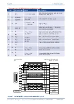
Pin assignment X2B Analog incremental encoder
Pin No.
Denomination
Value
Specification
1
MT+
+ 3.3 V / Ri = 2 k
Motor temperature sensor, normally closed
contact, PTC, NTC, KTY...
9
5 V ... 12 V
R
I
1 k
Sensor input for encoder supply
2
U_SENS-
10
US
5 V / 12 V /
10%
I
max
= 300 mA
Supply voltage
3
GND / MT-
0 V
Reference potential Supply voltage and
motor temperature sensor
11
R
0.2 V
pp
… 0.8 V
pp
RI
120
Reset pulse trace signal (differential) from high-
resolution incremental encoder
4
#R
12
COS_Z1 / D
1 V
pp
/
10%
RI
120
COSINE commutation signal (differential) from
high-resolution incremental encoder
5
#COS_Z1 / #D
13
SIN_Z1 / C
1 V
pp
/
10%
RI
120
SINE commutation signal (differential) from
high-resolution incremental encoder
6
#SIN_Z1 / #C
14
COS_Z0 / B
1 V
pp
/
10%
RI
120
COSINE trace signal (differential) from high-
resolution incremental encoder
7
#COS_Z0 / #B
15
SIN_Z0 / A
1 V
pp
/
10%
RI
120
SINE trace signal (differential) from high-
resolution incremental encoder
8
#SIN_Z0 / #A
Output of the analog incremental
encoder interface at the motor
D-SUB connector at
X2B
Backplane
Control Cabinet
Cable shield
(optional)
Connector housing
2
3
4
5
9
10
11
1
12
6
7
8
13
14
15
1
9
8
15
COS_Z0
#COS_Z0
#SIN_Z1
#SIN_Z0
SIN_Z1
#COS_Z1
COS_Z1
#R
SIN_Z0
R
GND
US
U_SENS-
MT+
MT- (AGND)
Male
Figure 27: Pin assignment: Analog incremental encoder [X2B]


