


Page 62
Electrical installation
Product Manual / Mounting Instructions
„Servo drives ARS 2320 FS, ARS 2340 FS and ARS 2360W FS“
Version 1.0
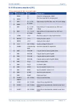
8.6 Resolver [X2A]
Pin assignment X2A Resolver
Pin No.
Denomination
Value
Specification
1
S2
3,5V
RMS
/ 5-10kHz
R
i
> 5k
SINE trace signal, differential
6
S4
2
S1
3,5V
RMS
/ 5-10kHz
R
i
> 5k
COSINE trace signal, differential
7
S3
3
AGND
0V
Shield for signal pairs (inner shield)
8
MT-
GND (0 V)
Reference potential temperature sensor
4
R1
7V
RMS
/ 5-10kHz
I
A
150mA
RMS
Carrier signal for resolver
9
R2
GND (0V)
5
MT+
+3,3V / Ri=2k
Motor temperature sensor, normally closed
contact, PTC, NTC, KTY
INFORMATION
The Motor temperature sensor can either be connected to X2A or X2B. It is not
possible to connect multiple sensors.
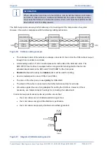
INFORMATION
In addition, a low-impedance connection of the outer cable shield to the housing of the
servo drive has to be established. Therefore, the outer cable shield of the angle
encoder cable must be connected to the housing of the angle encoder connector.
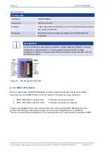
2
3
4
5
6
7
8
1
9
Backplane
Control Cabinet
1
5
9
6
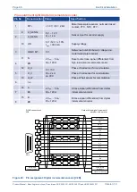
Cable shield
(optional)
S3 / COS-
S1 / COS+
S2 / SIN+
MT- (AGND)
R1 /
R2 / Carrier-
MT+
S4 / SIN-
Resolver output at the
motor
D-SUB connector at
X2A
Male
Connector housing
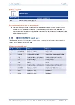
Figure 25: Pin assignment: Resolver connection [X2A]
The outer shield is always connected to PE (connector housing) on the servo drive.
The three inner shields are connected on one side of the servo drive ARS 2300 FS to Pin 3 of [X2A].


