5 Theory and internal operation
79
5.1.8 Harmonics
Standard compliance:
IEC 61000-4-30 Class A and S (Section 5.7)
IEC
61000-4-7
Class
I
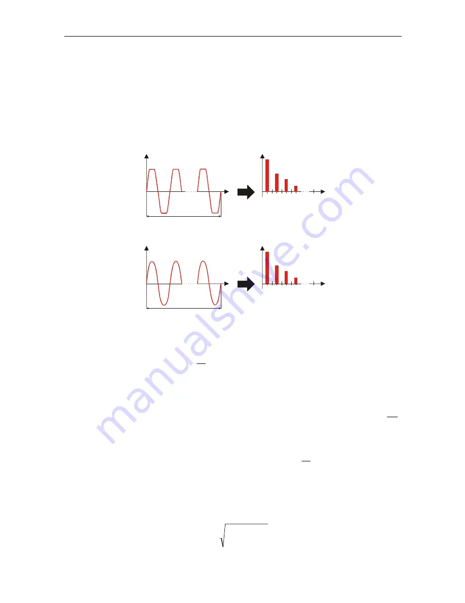
Calculation called fast Fourier transformation (FFT) is used to translate AD converted
input signal to sinusoidal components. The following equation describes relation
between input signal and its frequency presentation.
FFT
Voltage harmonics and THD
10 periods
t
n
1 2 3 4 5 6
50
U
FFT
10 periods
t
n
1 2 3 4 5 6
50
I
Uh
n
Ih
n
Current harmonics and THD
Figure 5.4: Current and voltage harmonics
⎟
⎠
⎞
⎜
⎝
⎛
+
⋅
+
=
∑
=
k
k
k
t
f
k
c
c
t
u
ϕ
π
1
512
1
0
2
10
sin
)
(
(17)
f
1
– frequency of signal fundamental (in example: 50 Hz)
c
0
– DC component
k – ordinal number (order of the spectral line) related to the frequency basis
N
C
T
f
1
1
=
T
N
– is the width (or duration) of the time window (T
N
= N*T
1
; T
1
=1/f
1
). Time window is
that time span of a time function over which the Fourier transform is performed.
c
k
– is the amplitude of the component with frequency
1
10
f
k
f
Ck
=
ϕ
k
– is the phase of the component c
k
U
c,k
– is the RMS value of component c
k
Phase voltage and current harmonics are calculated as RMS value of harmonic
subgroup
(sg)
: square root of the sum of the squares of the RMS value of a harmonic
and the two spectral components immediately adjacent to it.
n-th voltage harmonic:
∑
−
=
+
⋅
=
1
1
2
)
10
(
,
k
k
n
C
n
p
U
h
U
p: 1,2,3
(18)


