background image

16

      4.3. Logging & Reports

   - Logging data creates a logfile (.csv) and a Measurement Report
   - Pressure Decay Test creates a logfile (.csv) and a Pressure Decay Test Report (long & short)
   - Vacuum Decay Test creates a logfile (.csv) and a Vaccum Decay Test Report (long & short)

            • Logging

When you apply ‘logging’, the measured values will be memorised with a standard interval of 
5 seconds. This data can be used in Measurement Reports. You’re getting a list of saved data 
(time & value) that you can retrieve from the Metreco on your PC via USB. This can then be 
used for technical or commercial purposes (see ‘4.5. Customer & Systems follow-up’

).

           The standard interval between 2 loggings is 5 seconds. You can modify this interval in 
the configuration menu (see ‘3. Configuration’).

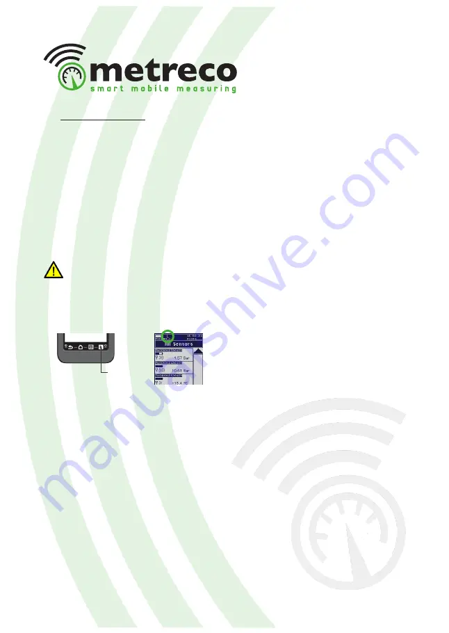
1. Select ‘Logging’ to start the logging process. The logging icon ‘L’ will start blinking.
2. Select ‘Logging’ again to end the process. The logging icon ‘L’ will stop blinking.

When you end the logging process, a new Measurement report with the last logged measured 
values is automatically created (see next point -> Measurement Report), all the logged values 
are saved in a ‘LOG’ file (.csv).

There are over 1.000.000.000 data points...

Logging

Summary of Contents for HH02ST

Page 1: ...English v1 3 metreco MANUAL Metreco HVAC MK1...

Page 2: ...s and warnings indicated in this manual are marked with the following symbol IP64 dust tight splashingwater tight don t submerse or hold under tap upside down can be used in the rain Do not open in or...

Page 3: ...Diagnosis Measurements Diagnosis 4 3 Logging Reports Logging Measurement Report Intervention Report 4 4 Tests Pressure DecayTest Vacuum DecayTest COPTest 4 5 Customer Systems follow up Follow up on M...

Page 4: ...rements simultaneously to the Handheld no hoses no lines The user positions himself where he wants walks around and can read out the measurements in real time Intuitive natural easy to use interface i...

Page 5: ...ooking at the All Measurements level and has an instant idea of the measured and calculated values If one of the targets is off he gets a warning with a diagnosis and a possible cause The measured val...

Page 6: ...E Male 5 16 SAE Female 1 X connector 4 1 4 SAE Male 2T connectors 1 4 SAE Female 2 1 4 SAE Male Space for 3 extra sensors Sensors Charging LED Handheld Lid with protective foam Storage Socket for char...

Page 7: ...ors to Main Menu start stop logging 1 4 3 2 Touchscreen Shortcuts Power sockets USB socket Power sockets ON OFF Calibration Locate Red LED Green LED Push the button while the red LED flashes 2 s Flash...

Page 8: ...rmware see 5 3 Units Language Log interval go to 4 3 Logging Date andTime 3 Change the configurations as desired 2 Select Configurations Target margins Screen intensity 1 Go to Main Menu Modifying the...

Page 9: ...em and turn them on by pressing at least for 2 seconds on the button 4 Observe the measured values 2 You will see the All Sensors screen In chapter 4 ACR the following applications are treated Creatin...

Page 10: ...tem choose an existing ACR system edit current ACR system remove an existing ACR system 1 Choose New ACR System and select Client Create a new one if needed or select an existing one 2 Choose Name and...

Page 11: ...or The sensor code will start blinking on the handheld 11 When all sensors are assigned select OK in the right bottom corner This will give you the ACR Sytem again 8 You have the possibility to assign...

Page 12: ...e to re enter the data at each service 4 Select the customer whose system you are servicing 5 Select the ACR system 10 Observe the measured values in AllValues Choose existing ACR system 3 Select Choo...

Page 13: ...an undo it s placement and assign it on a different spot system can be saved without sensors being placed 5 Confirm with OK 6 Save System Edit current ACR system Saved systems can be removed deleted 1...

Page 14: ...erature at evaporator inlet Air temperature at evaporator outlet Temperature Delta of air over evaporator Pressure at condensor outlet Pressure Delta over condensor Pressure at filter outlet Pressure...

Page 15: ...non limited list that serves only as an indication The engineer has to make his own diagnosis and has to be in possession of the certificates mandatory by law and the knowledge to service ACR systems...

Page 16: ...the Metreco on your PC via USB This can then be used for technical or commercial purposes see 4 5 Customer Systems follow up The standard interval between 2 loggings is 5 seconds You can modify this i...

Page 17: ...ending the logging and can be recalled on Metreco and downloaded on PC for later use in internal reports or reports to your customer 5 The Measurement Report contains a summary of customer data system...

Page 18: ...rigerant acid test refrigerant moisture test Time spent on the job Notes 1 Select a system see 4 1 Intervention Reports can only be made when an ACR system is selected 3 Select New Intervention Report...

Page 19: ...um sensor if placed on the installation and assigned in Metreco 11 Select the used gas N2 or N2 H2 17 Select Moisture test and enter the result 19 Select Notes and add remarks 16 Select Acid test and...

Page 20: ...the Pressure DecayTest Setup You must assign a pressure sensor You are free to choose to assign a SystemTemperature sensor AmbientTemperature sensor Target Pressure Pressure Medium N2 or N2H2 1 Selec...

Page 21: ...he System Temperature TargetVacuum Pressure 1 Select Main Menu and select Tests 4 Press Start Evacuation You get theVacuum Evacuation Status 5 When the wanted target vacuum is achieved stop de evacuat...

Page 22: ...measuring the Seasonal COP 2 Select COPTest 3 Complete the COPTest Setup You must assign at least 2 pressure sensors and 3 temperature sensors A third pressure sensor is needed if your refrigerant has...

Page 23: ...nect to your PC with the included USB cable 2 Select Open folder to view files using 3 You get 5 folders handheld data file not for manipulation lang all languages logfiles data file not for manipulat...

Page 24: ...yTest Report long short version repeat step 1 to 6 7 Select REPORT 8 Select the wanted report type 9 Select the wanted report 10 The reports can be opened using any conventional word processor Click r...

Page 25: ...l be lost Sensor out of range If your sensor is out of range all arrows will have disappeared in the reception area of that target sensor in the All Sensors screen see step 4 in 3 Measuring during the...

Page 26: ...g removing and handling refrigerant 4 Hoses 1 4 SAE 1 4 SAE Red Blue Yellow 1 4 SAE 3 8 SAE Yellow 2T connectors 1 4 SAE Female 2 1 4 SAE Male 1 X connector 4 1 4 SAE Male 2 R410A adaptors 1 4 SAE Mal...

Page 27: ...27 Evacuation 1 Evacuation 2 Evacuation 3 X connector...

Page 28: ...han the one you have on your Metreco see step 5 below 5 2 Calibration We advice you to in the spirit of the F GAS have your sensors tested and calibrated yearly You can perform the sensor calibration...

Page 29: ...is window and disconnect your Metreco 3 Connect the Metreco to your PC with the included USB cable 4 Select Open folder to view files using 5 Drag the downloaded file s in the dedicated folder Langaug...

Page 30: ...n air Protection IP64 with cap closed Temperature Code Tc0150PV Name Temperature sensor Range 50 150 C Precision 0 5 C Autonomy ON 119h 5days Autonomie OFF 1 5 year Battery LiPo Lithium Ion Polymer Wi...

Page 31: ...absolute vacuum gauge precision 0 5 50 150 C temperature sensor Velcro standard Metreco case charging station standard accessories for Metreco hoses couplers adaptors USB cable red hose 1 4 SAE 1 4 SA...

Page 32: ...www metreco com T 32 58 42 91 00 info metreco com F 32 58 42 14 46...

Page 33: ......

Reviews: