56
Technical Bulletin—TC-9100 Universal Controller
To reach the jumpers and switches, open the controller by gripping the
cover with thumb and finger on both sides above center and pull the
cover off using the lower edge as a hinge. Replace the cover by resting
the lower edge of the cover against the base and then pressing the cover
firmly to engage all four retaining lugs.
If the controller is connected to a communications bus, a network address
must be set. Refer to the project documentation for the correct address
setting for the controller. Addresses 0 to 255 can be set on the address
switches as follows:
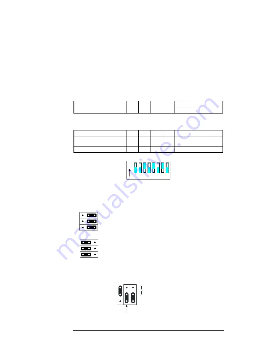
The setting on the Address Switches is in binary format:
Switch
Number
1 2 3 4 5 6 7 8
Decimal
Equivalent
1 2 4 8 16 32 64
128
Example (Address 171):
Switch
Number
1 2 3 4 5 6 7 8
Switch Position
ON
ON
OF
F
ON OF
F
ON OF
F
ON
Decimal Equivalent:
171 =
1 +
2 +
0 +
8 +
0 +
32 +
0 +
128
Address Switches set to
Address 171
ON
2 3 4 5 6 7 8
1
The jumpers on jumper block JP3 are used to select the type of room
command module as follows:
utc0jmrs
Jumpers are inserted to the right positions for the
RS-1100
series room module (factory default).
utc0jmtm
Jumpers are inserted to the left positions for the
TM-9180 Room Command Module.
The jumpers on jumper block JP4 are used to select the types of analog
outputs (only on models that have analog outputs), as follows:
JP4
Jumper in this position selects
0-10V output
AO2
AO1a
AO1b
PWM Not used
Figure 26: Jumper Settings for Analog Output Types
Jumper and
Switch
Selections
Address
Switches
Jumpers


