


SQA-Vision
Service Manual Version 109.13.4
Edition rev.: Jan 2020
9
SECTION IV: System Components and Accessories
Testing
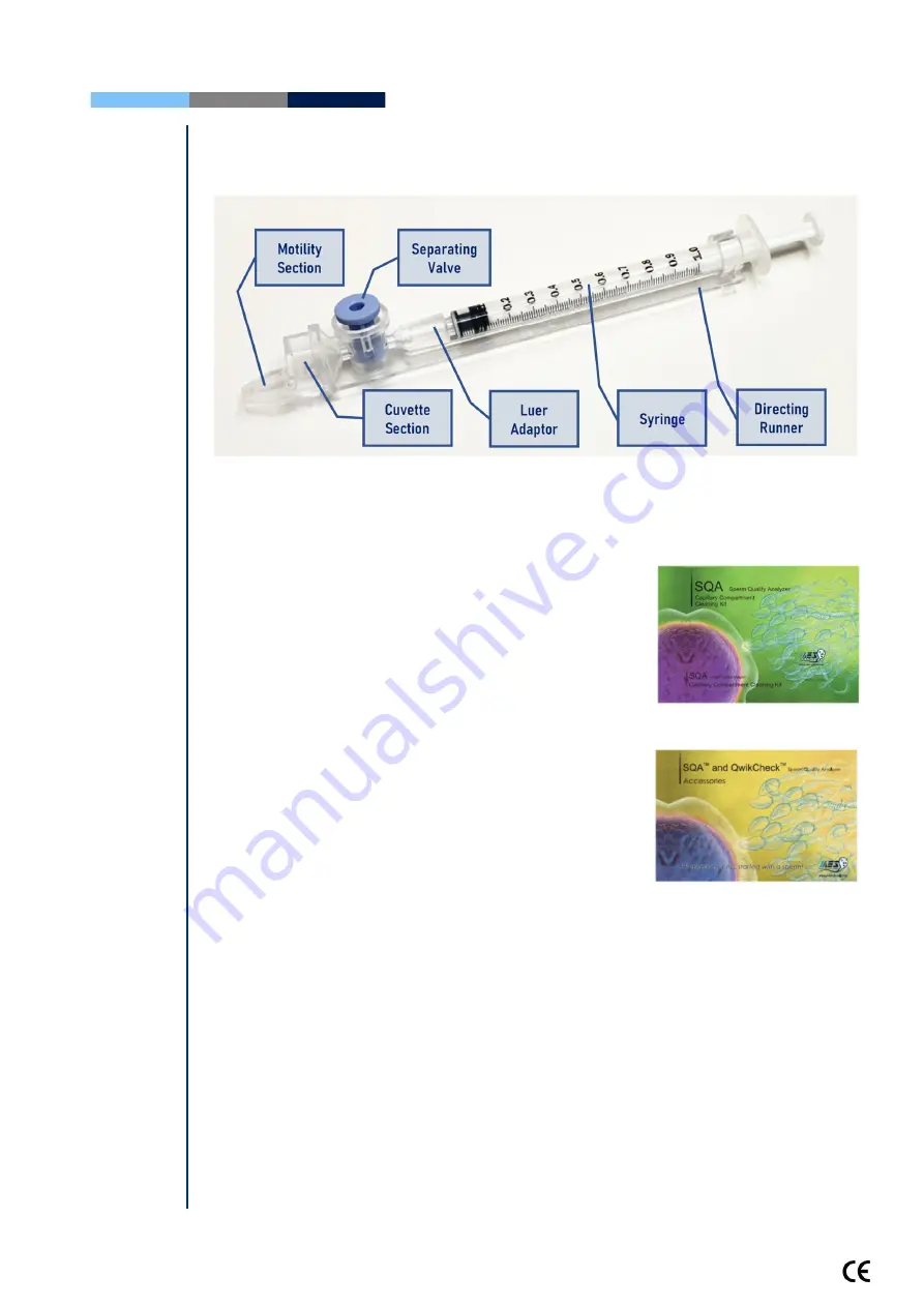
Capillary
Testing Capillary
Can be used in both measurement chambers of the SQA-Vision.
Disposable; designed to collect and test samples in a biologically safe manner.
Motility is measured in the 0.3 mm (thin) "Capillary Section."
Concentration is measured in the 10 mm (tall) "Cuvette Section."
Cleaning Kit
Cleaning Kit
Daily cleaning is recommended or after testing 10-
15 specimens.
See the detailed cleaning instructions in the
Appendix Section.
Note:
Only use the manufacturer’s cleaning kit or
the SQA-Vision can be damaged.
Accessories Kit
Accessories Kit
Each kit contains:
Power Cables
Communication Cable
USB cables
RS232 cable
RS232 to USB converter
Instructional Guides
Slide holder
Additional set of device feet
Barcode reader
Capillary piston – Opening and Removal Jig
Self-Test and
Auto-
Calibration
Start-up
Section V: Self-Test and Auto Calibration
The SQA-Vision automatically runs a series of tests to check calibration settings and the
internal operating system. Tests are run when the system is turned on and prior to
testing a sample.
Start-up:
Stabilization and autocalibration:
Checks system stability and reference parameters.
The system sensors are analyzed for several minutes to ensure that the reference
parameters are within acceptable ranges. Once the system is stable for 30 seconds it will
pass stabilization and autocalibration. A warning message of the system stabilization


